Finding the Fault on Twisted Pairs
There are a lot of anomalies found on a typical time domain reflectometer (TDR) trace. Cables themselves are not consistent in composition. Finding where the fault is versus the characteristics of the cable can be tricky.
TDRs help facilitate recognition location of the actual fault against the normal quality of the cable. TDR operators can manipulate pulse width and gain to distinguish a fault from the characteristics of the cable they are testing. TDRs offer the most accurate, reliable, and consistent testing of underground copper lines, with little to no human error. They are far superior to older technology like surge generators that locate faults via "thumping".
"Think of the TDR as a radar gun like a state trooper would use on the highway to catch you for speeding. The TDR measures the time it takes the pulse to travel down a cable, echo and return to the source."
Out With The Old, In With The New
In short, thumping is run by a dc power supply, an hv capacitor, and an hv switch. The dc power supply charges the capacitor, which then closes the switch as the surge travels down the cable on the hv conductor. If the voltage is high enough, the fault will break down and the energy for the capacitor will flash over causing a "thump" at the site of the fault. It is then the operator’s job to find the fault by walking the line and observing the area. As you can imagine, this technique can include high counts of human error.
Modern testers, like TDRs, offer the most straight-forward testing technique with the most precise results. These testers typically have the option of being run automatically (for ease of operation) with the press of a button or being operated manually by an experienced technician. Either way, results are nearly 100% accurate.
A TDR is not merely a useful tool, it is in fact invaluable in finding faults on metallic cabling like twisted pairs, concentric, hot and neutral, conductor and shield, two phases or any similar combination (it will not work on single-conductor cable).
Behind the Scenes
TDRs send an energy pulse down 2 metallic conductors and are affected by the composition of the insulation in between. When the pulse encounters a change in impedance of the insulation, a portion of the energy is echoed back, while the remainder continues to travel down the cable and eventually echo off the termination.
Think of the TDR as a radar gun like a state trooper would use on the highway to catch you for speeding. The TDR measures the time it takes the pulse to travel down a cable, echo, and return to the source. The speed of the signal is then multiplied by the time it takes to return to the source, and is then divided in half (to the fault and then back). This equation gives the distance to the fault. In order for the unit to calculate this, it must know the speed of the impulse.
On a highway, that is determined by the air. On a cable, the determination depends on the type of insulating material used. Each type of insulation (EPR, XLPE, PILC, etc.) allows the impulse to travel at a specific speed called velocity of propagation (VoP). The operator finds the VoP on a table, as well as the specs of the cable being tested, and enters it into the tester. These numbers can usually be found in an onboard library of high-quality testers.
In an ideal world, the cable would be perfect and all would go easy breezy. But as with all things in life, nothing is perfect and neither are cables. Each is manufactured with varying degrees of quality. The thickness of the insulating layer may not be uniform, the conductors may not be parallel and the materials may contain voids and other imperfections. And as we all know, over time stress and strain and the elements all play a role in deteriorating cable lines — hence why there is a fault in the first place. This is why it is important to have a quality tester and an experienced operator at the helm to take accurate measurements.
Arc Reflection: When Old and New Meet
Earlier we said that thumping is not ideal in finding a trace; however, when it is used in conjunction with a TDR it creates a technique called arc reflection. This method combines the best features using a surge generator (thumper) and TDR along with an arc reflection filter; the thumper creates an arc which couples with the TDR pulse that then sends back the reflection that is traced in the display. The filter protects the TDR from the high-voltage surge and routes the low-voltage pulse down the cable. The thumping picks up the high-resistance faults that the TDR misses, while the TDR limits the time spent thumping.
This method is not only a time saver, as it could take hours to walk the line looking for the fault, it also reduces the stress on the cable dramatically in comparison to pure thumping. The TDR also produces a complex trace which is great for analyzing the cable’s condition like the presence of multiple faults, taps, splices, and bridges.
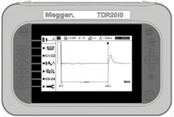
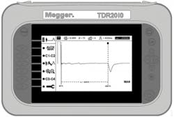
Different types of faults give different shapes to their reflections.A "perfect" cable that is tested with a TDR will show a reflection at the end of the cable (upward for "open" and downward for "short") with a perfectly flat line in between. If there is a fault, another reflection will appear somewhere along the line corresponding with its location so the operator can determine the nature of the problem based on its shape. (See Figures 1 and 2.)
Figure 1. Trace of an "open" — positive reflection — conductors moving apart.
Figure 2. Trace of a "short" — negative reflection — conductors moving closer together.
Take a splice for example. A splice will have a distinct shape. If the operator knows of a splice on the cable prior to testing, it can be disregarded on the trace and he can move on to the next reflection. If the location of a splice is known, it can then be used as a landmark to better position an existing fault.
Determining which reflection is caused by a fault and affecting operation of the cable can be difficult. That is why the enhanced features of a TDR play an important role in finding these faults.
Understanding Pulse Width
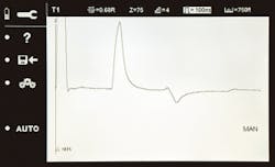
A valuable function that all operators should understand and use is the pulse width. This is the duration of the energy pulse that will echo from the fault or other event. It is expressed in nano-seconds (ns), with typical values from a few ns to several milli-seconds. It is driven by just a few volts of electro-motive force (emf). (See Figure 3.)
Figure 3. Short pulse width separates near-end fault from input surge.
Like much of electrical testing, the best use of pulse width includes an element of compromise. Longer pulse widths travel farther and determine that length of cable that can be observed on a single trace. But a long pulse width can obscure 2 events that are close together by including them as a single event. This is most often a problem where the fault is at the beginning of the line, right at the operator’s feet. This is usually the case, as cable terminations can readily be made incorrectly and include a fault.
All TDRs produce an initial upward trace from the change in impedance where the connection is made from the tester to the cable being tested. The shorter the pulse width, the more likely the fault will be revealed as separate from the initial surge.
Sophisticated testers will sense the properties of the cable and automatically make a judicious selection of pulse width. From there, the skilled operator can manually adjust the width to ferret out difficult events. A minimal 2 ns pulse width, available in top quality testers, affords the operator maximum capability to recognize near-end faults.
Simple vs. Dual
Simple TDR models give users a single trace, and while they are fine for most applications, like twisted pair, they won’t find every fault in a line. They will reliably locate opens and bolted shorts; however, on larger gauge and more complex power cables, high resistance faults are harder to identify and may require additional features. (See Figure 4.)
Figure 4. Single-trace TDR can find most common faults.
For more demanding applications, dual channel models are necessary to gather all the information needed. These models offer critical, advanced technology that will identify many additional faults in a full-featured dual trace TDR.
Dual trace models have 2 parallel channels that can be engaged separately or in tandem, providing an advantage in locating faults that are difficult to find. It is sometimes valuable to have 2 traces simultaneously on the screen to automatically make various types comparisons. Sophisticated TDRs can make the same comparisons that it used to take a skilled operator to make.
Dual models are able to save all data and traces to be used at a later time. The dual trace can easily help facilitate the process of locating a problem — pinpointing where the location of an event is based on a comparison of information between the cable’s initial installation results from the TDR and the current results showing a fault.
A more sophisticated instrument can read 2 traces that are at different ranges, and have their own setup and zoom capabilities. For example, on a twisted pair a suspected faulted pair can be connected to 1 channel while a known good pair is connected to another, the difference between the reflections are noted.
Fault Locating Best Practices
Historical data plays a significant role in locating faults quickly and accurately. Cables should be tested at the time of installation, then again at maintenance and repair. All of these traces should be stored for a later date, should a comparison be needed.
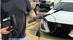
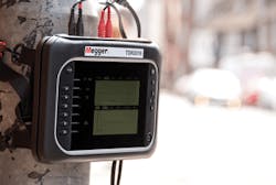
Figure 5. Dual channel TDRs allow outdoor field operation.
Certain TDRs allow operators to add and subtract traces. Rather than displaying an entire trace that may include several insignificant imperfections, the TDR can subtract 1 channel from another and display only the section or sections that differ.
Newer units offer the ability to color code traces. Since dual traces crisscross one another and create complex patterns, the ability to assign different colors to different trace lines is extremely effective in interpreting intricate traces. (See Figure 5.)
Distribution cabling is an interesting example. Individual customers are connected to a feed line via a hard-wired tee joint. These feed lines can be numerous, making the TDR trace difficult to interpret. Joints on the main cable as well as each individual line are reflected leading back to the customers and to the trace. These diversions decrease the distance that can be tested accurately and effectively.
Dual trace testers can overcome these obstacles in 3 ways.
First, ng is by overlaying a current trace with a historical one showing where the faults are in the line.
Second, a comparison can be made before and after a line has been conditioned, like high potting or burning the fault.
A final way is to run 2 separate traces simultaneously. For example, a 3-phase cable with an open on 1 phase; 1 channel can be connected across A and B phases while the other channel across B and C. The point in which there is a pronounced deviation is where the fault lies.
Over the years equipment has evolved from crude listening techniques to sophisticated technology incorporating safety, accuracy and speed. However, operator judgement, experience, and knowledge still play a big part in accurately finding faults in a timely manner. By combining these two, and knowing your application, finding the fault should be a snap.
