

How to Choose the Right Fusion Splicer for Your Application
Fusion splicing has long been the preferred method for permanent construction of fiber optic networks. Throughout the late 1990s and early 2000s manufacturers focused primarily on size and portability, along with faster cycle times, to complement these precision instruments. In more recent years, as splicing activities have moved further into the network, and often to remote outdoor locations, splicer manufacturers have focused on developing ruggedized products that can withstand severe impacts and exposure to outdoor elements such as dirt, wind, and rain.
Even greater decreases in cycle time have been achieved recently with many manufacturers offering core alignment models delivering sub 10-second splice times and sub 15-second heating times for splice protection sleeves. Compared to the nearly 5-minute total cycle times of the early 1990s, splicing productivity in 2016 has come a long way!
Today, there are many varieties and options to consider when purchasing a fusion splicer. That’s why it’s important to know the differences between 3 types that are used for single fiber applications:
Type A: Fixed V-Groove
Type B: Active Cladding Alignment Splicer
Type C: Active Core Alignment
Type A: Fixed V-Groove Models
These low-cost splicers typically have 2 motors which are used to move the fibers in the Z direction for gap setting and splicing. The optical systems in these machines are capable of measuring cladding alignment, and the v-grooves are in a fixed position, which does not allow mechanical movements for cladding alignment to take place.
Because of the limited number of motors, fixed v-groove splicers are often the smallest machines available. Many manufacturers offer models that are small enough to slip into a jacket pocket, as well as full-sized machines with larger monitors and batteries.
An important consideration with a fixed v-groove splicer is the required level of cleanliness that is needed for proper operation. With the threshold for cladding misalignment typically in the 5 µm range, it is not uncommon for some users to struggle with frequent cladding misalignment errors. Proper cleaning techniques are critical to minimizing these errors.
Type B: Active Cladding Alignment Splicer Models
Although these models use a similar optical system as the fixed-groove models, 2 motors are added to provide the capability of moving the v-grooves: 1 in the X direction and the other in the Y direction.
With the addition of these motors, perfect cladding alignment can be accomplished even with small levels
of dust or other contaminants present in the v-grooves. This results in similar splice loss levels as a fixed v-groove model, but without the need for careful attention to the cleanliness of the v-grooves, and, most importantly, without cladding offset alarms that can become annoying with a fixed v-groove splicer that is not well maintained.
It is important for users to understand that the splice loss performance of both fixed and active cladding alignment machines is limited by fiber geometry accuracies. While most fibers produced today yield reasonable splice loss when only cladding alignment is used, some are clearly better than others. Because the optical systems in both fixed v-groove and active clad alignment systems do not analyze the alignment of the core, the resulting splice loss estimates are calculated with the assumption of reasonable levels of core cladding concentricity. Therefore, it is almost inevitable for situations to arise where the actual splice loss varies from the estimated splice loss by a noticeable amount.
Type C: Active Core Alignment Models
This is the most accurate, and generally the most preferred, of single fiber splicing machines. In these models 2 additional motors (6 total) are added to allow the precision focusing that is needed to accurately detect, measure and align the core of an optical fiber.
The objective lenses and other optical components are usually of the highest quality, and are individually tested and matched to the electronics via proprietary software.
Leading suppliers have been producing machines capable of consistently delivering an average splice loss
of ~0.02 db with common single-mode fiber for nearly 30 years. Advanced features such as eccentricity correction are often present to ensure low loss splice results regardless of fiber quality. And because alignment is based on core position, the loss estimation of true core alignment models is the most accurate available.
These machines are the product of choice by independent installers for their consistent performance and reliability. Returning to a job site to address splices that are later found to be out of specification is a costly endeavor that most wish to avoid.
Core alignment splicers are also where you’ll find the most variations in performance. In Figure 1, 6 splicer brands were tested using single mode fiber of various quality. While splice loss of "good quality" single mode fiber was relatively consistent, the splice loss results documented when splicing higher eccentricity single mode fiber highlight that various levels of core alignment capability can be found amongst brands; some may even claim core alignment when only active cladding alignment is being used.

Figure 1.
Options, Options, Options
Many brands and models offer a variety of features to allow a high level of customization to suit individual user preferences. For example:
• In many models, the tube heater can be used in the front or rear of the splicer, depending upon workflow preference.
• Many single fiber splicing machines, which have historically been supplied with hinged clamps for securing the fiber in the machine, now have removable clamps that also allow fiber holders to be used instead.
• Infrequent users often prefer fiber holders for the ease of use in cleaving and loading the fiber into the machine, while those focused on production needs typically prefer the hinged clamps due to faster processing times.
• Some models even have automated and programmable opening and closing of the wind protector, and clamps to enable faster cycle times.
If a ribbon splicer is desired, the selection process gets much easier. All multiple fiber splicing machines offered today use the same fixed v-groove technology discussed previously. Manufacturers generally offer only one 12-fiber version, and some offer a 4-fiber version as well.
While it might seem that most products would perform equally, especially since fixed v-groove alignment is used, the reality is that there is quite a bit of technology involved in properly fusing multiple fibers.
A few critical items should be remembered:
• It’s critical to optimize the arc plasma field to allow an even application of heat to multiple fibers.
• Changes in elevation or barometric pressure have a significant impact on the heat generated by the arc of the electrodes.
• Users should understand what level of automatic versus manual adjustments might be required in the field, as this can be a time-consuming process.
• Splice-on connectors have become extremely popular. These are pre-polished and can be spliced with a fusion splicer very close to the exit of the ferrule. Rather than splicing a pigtail, drop cables and patch cords can now be custom-built to length in the field. The primary benefit is the elimination of the requirement for slack storage of the cable.
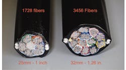
• Patch panel upgrades of older-generation connector technology are also popular. Figures 2 and 3 show one type called FUSEConnect®. These connectors are factory polished, cleaved, and provided with a disposable fiber holder. Once opened, the fiber holder is simply placed in the splicer, and the fiber to be connectorized is prepared by installing the connector parts prior to splicing. Once the fusion splice is complete, the heat shrink sleeve is applied, and the remaining parts are installed to form a completed connector.

Figure 2.

Figure 3.
If you are in the market to purchase a fusion splicer and are unsure what brand or model to buy, take the time to test drive a few. And remember, you don’t have to go it alone: use the following "Check It Out" checklist.
Check It Out
In the market for a splicer? Use this checklist to find the right fit for your application.
1. Any reputable supplier will spend the time needed to understand your application. Be sure they let you test a machine in field conditions.
2. Advancements in fiber technology, especially bend-insensitive fibers, are rapidly taking place. Be sure the splicer manufacturer has knowledge of the industry, and can address new fiber types as they are released to the market.
3. Look closely at the cost of any optional items you feel you might need. Prices on accessory items can vary widely, and the differences can quickly offset any differences in the splicer pricing that may exist.
4. Find out what is covered under the warranty term. Many splicers returned for service are really not "defects in materials and workmanship" but were not cleaned properly. Are you going to be charged for that?
5. Evaluate the reputation for product support and service turnaround time. In most cases problems arise when you are using the machine, and quick turnaround can result in considerable savings by avoiding downtime.
6. Ask your competitors, contractors, and installers what brands are preferred in the field and why.
Save
Save
Save
Save
Save
Save
Save
Save
Save