
By Ken Fridley and Keith Foord
Since the introduction of optical networks in the late 1970s, the goal for service providers has been to leverage the higher bandwidth, robust operation, and cost reductions provided.
Today, with multiple vendors and standards to choose from, operators need to consider which optical access platform allows their plant to adapt cost-effectively and intelligently as technology evolves. And since the outside plant (OSP) accounts for approximately 70% of the total investment in FTTH networks, coexistence between existing equipment and the OSP is imperative for any technology migration.
NG-PON2 Overview
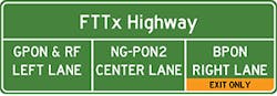
Passive optical networks (PON) deployments efficiently utilize fiber infrastructure with 2 ITU-T standards: G.983 BPON, G.984 GPON. Responding to demand for faster network speeds to serve business, residential and backhaul customers while coexisting with GPON networks, the ITU-T recently ratified a new standard, G.989 NG-PON2, based on tunable wave-division multiplexing (TWDM). The new standard supporting speeds of 80×10 Gbps downstream/upstream at distances up to 80 km. The future of NG-PON technology is bright, with 100 Gbps data rates over distances more than 100 km expected to be commercially available by 2025 or earlier. (See Figure 1.)

Figure 1. PON Band Plans
NG-PON2 mandates WDM channel separation from existing GPON and RFoG wavelengths and supports a "pay as you grow" deployment strategy, enabling performance upgrades without disrupting customers currently on GPON. Coexistence with GPON requires installation of a passive coexistence element (CE) where OLTs combine to separate the various wavelengths associated with GPON/NG-PON2. While BPON networks do not require conversion to GPON prior to implementing NG-PON2, upgrades will be very challenging because the entire node requires slash cutting to new OLT/ONTs for all subscribers on the node simultaneously. This can require significant down time for existing customers.
If BPON is currently deployed, a network overlay may be the easiest. That said, it may not be the most cost-efficient deployment path. In both cases installation of new NG-PON2 "colorless" ONTs is required as they are capable of rapidly shifting to any assigned wavelength. (See Figure 2.)
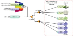
Figure 2. NG-PON2 Architecture
In addition, costs for NG-PON2 equipment is currently greater than GPON equipment but will continue to drop as adoption accelerates. NG-PON2 co-existence with RF video overlay is supported but may require compensation for Raman crosstalk impact on lower frequency RF channels. If RF is deployed, its coordination between the system vendor and the network operator during network design is critical.
In addition to increased bandwidth availability, 2 additional benefits of NG-PON2 compared to GPON is that the technology supports power-efficient modes of operation and robust carrier-grade resiliency. TWDM OLTs require up to 20 watts of power per port during active operation compared to 2 watts per port for GPON.
During off-peak traffic load periods, NG-PON2 ONTs can retune to a common wavelength handled by a single OLT port, allowing idled ports to be powered down and reducing the overhead cost of providing service. Given the higher power requirements of NG-PON2, cost savings are not just in electricity consumed by the line cards but also in other overhead costs such as system cooling and extended serviceable lifespan of system components. (See Figure 3.)
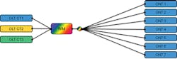
Figure 3. NG-PON2 Tunes to Common Wavelength to Save Power
NG-PON2 also supports robust path diversity and resiliency by provisioning separate primary and backup OLT systems as well as fiber runs on high value paths to a 2xN optical splitter. During normal operation, the network monitors OAM status information to detect if a fault has occurred. When this happens all affected ONTs quickly switch services over to a completely redundant (dual homed) OLT system. That system maintains full SLA capability or can retune to a common standby wavelength using a redundant shelf with a single backup CT which provides basic services until the fault is cleared. Regardless of backup architecture, ITU-T G.989.1 recommends service interruption time must be less than 50ms for enterprise or premium users. (See Figure 4.)
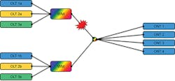
Figure 4. NG-PON2 Dual Homing Provides Fault Resiliency
Quality Practices
With over 80% of all failures in fiber optic networks being attributed to not cleaning or using improper cleaning methods, cleaning all network connections is of paramount importance when maintaining high bandwidth systems such as NG-PON2.
Fiber cleaning pens are a dry method of cleaning, and will clean to IEC61300-3-35 specification in most circumstances. They are easy to use, and effectively clean both the ferrule end face and the bulkhead. (See Figure 5.)

Figure 5. Clean Jumpers and Bulkheads Prior to Connection
If a connector is not cleanable, the wet/dry method can be used to clean stubborn contamination. The wet/dry method is comprised of placing a cleaning solution on a lint-free cloth, and running the ferrule end face across the moistened surface and then onto the dry portion of the lint-free cloth. Damaged connectors should be replaced as they are hard to clean, easily contaminated, and may cause permanent damage to any connector it is mated to.
At the very minimum, each connector and bulkhead should be visually inspected by the technician after cleaning and prior to connecting a connector to a bulkhead. For best network performance, each connector and bulkhead should be analyzed to the IEC61300-3-35 specification for a definitive Pass/Fail declaration. Connectors and bulkheads not cleaned and visually verified prior to connection will be prone to high loss and probable permanent damage which will degrade NG-PON2 performance.
Once the fiber is installed, basic loss testing should be performed to prove the fiber installation meets design specifications. This can be accomplished by using an individual laser and optical power meter (OPM) set or a fully automatic optical loss test set (OLTS).
Basic loss testing is comprised of zeroing the power meter, injecting a laser signal into the input side of the fiber link, and measuring the insertion loss of the fiber or device under test. Since the WDM is wavelength-specific, the technician will need to test at each WDM wavelength to fully qualify the network. Laser/OPM and OLTS methods of loss testing will not pinpoint where losses are, and give only a cumulative loss of the entire link.
Optical Time Domain Reflectometers (OTDR) can measure the entire length and qualify the fiber link providing documented insertion and return loss of every event as well as cumulative losses. Ideally the OTDR should be able to probe at each NG-PON2 wavelength.
At some point in time, the installed network may not function as specified or may experience a service failure, requiring an OTDR to troubleshoot the failure. To do this, a probe pulse is launched from the OTDR bulkhead, and as it propagates along the fiber some portion of the light is reflected to the OTDR from loss events or other discontinuities. From this returned signal, a trace representing the various loss events will be compiled and displayed by the OTDR for interpretation by the technician. The technician will then be able to pinpoint the offending component and make the necessary repair.
A simpler and lower-cost troubleshooting tool is a visual fault locator (VFL) which can be used to visually locate loss events where the technician can see the fiber optic cable. The VFL injects a visible red light into the fiber at a connector which will illuminate at a bad connector, macrobend, or break in the fiber. VFLs can also be used to confirm fiber continuity but should not be used to qualify a fiber link.
To prevent damage to eyes, the output of a VFL or fiber connector should never be directly viewed, and it is critical the VFL selected adheres to the Class 2 designation for safe output power levels as defined by the FDA. Technicians should never use a VFL with output power greater than 0dBm (1mW).
About the Authors: Ken Fridley is a Field Application Engineer at Greenlee Communications with over 26 years of experience in the telecommunications industry as a technician, manager, and trainer. For more information, please email [email protected] or visit www.greenleecommunications.com.
Keith Foord is a Product Manager at Greenlee Communications for fiber optic test instrumentation. He has more than 25 years of experience in the design and development of OTDRs, OLTSs, lasers, optical power meters, and other FO test instrumentation. For more information, please email [email protected] or visit www.greenleecommunications.com.
Save
Save