


The OPM Challenge —
I get no respect! Now I know what the optical power meter must feel like. With the OTDR being the key instrument for the outside plant (OSP) we tend to forget the one instrument that is cost-effective, traceable to calibration standards, and is used anywhere fiber optics is deployed.
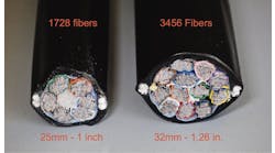
Today’s fiber optic communication systems are changing quickly to address the demands of higher speeds with greater reliability. Fiber-to-the-home (FTTH) and fiber-to-the-antenna (FTTA) installations are being installed in massive deployments. This in turn is stressing the bandwidth requirements of feeder and distribution routes. In many cases this is due to the limited fiber counts that were available when many of these installations originally occurred. Called fiber exhaust this situation forces service providers to either install a new higher fiber count cable or use the existing cable by increasing the system speeds via time division multiplexing and/or the use of optical wavelength division multiplexing (WDM).
And with those technology changes, optical power levels can change dramatically.

Testing an optical line terminal with an OPM.
The essential tool used in measuring optical power is the optical power meter (OPM) which receives the optical signal and measures its power level through its large area photodiode. The OPM is designed to receive the optical power using its area detector to efficiently collect light defined by the single-mode fiber. Not only is the detector large in size but it also receives light from a broad spectral range, making it ideal for most tests and measurements.
Optical power is expressed in dBm, or decibels referenced to 1 milliwatt. Once I know the output power of a transmitter and the receive level of a receiver, I can quickly identify the loss in the OSP by subtracting the two measurements from each other (dBm – dBm = dB). For example, if 0 dBm equals 1 milliwatt, then -10 dBm is one tenth of 1 milliwatt, and +10 dBm is 10 times 1 milliwatt or 10 milliwatts. For this reason, all documented optical power measurements must be recorded as either as a plus or minus reading (e.g., -32 dBm).
Because the power and attenuation measurements made with an OPM are the cornerstone of the fiber measurements, the OPM must produce accurate results which is why the OPM requires periodic calibration traceable to the National Institute of Standards Technology (NIST) to ensure accurate measurements. OPMs can be calibrated by the original manufacturer but also by calibration organizations with NIST traceability.
Tip: When contracting test work out, it is important to request a copy of the calibration certificate from your contractors to confirm that the optical measurements made with the OPM comply with industry test and measurement standards.

InvisiLight® Solution for Deploying Fiber
April 2, 2022
Go to Market Faster. Speed up Network Deployment
April 2, 2022
Episode 10: Fiber Optic Closure Specs Explained…
April 1, 2022
Food for Thought from Our 2022 ICT Visionaries
April 1, 2022Testing Transmitters and Receivers
Acceptance testing of transmitters and receivers is important to verify that they meet the manufacturer’s specifications as well as any specified performance levels. It also provides an opportunity to document their characteristics to serve as a benchmark for proper maintenance and restoration benchmarks. Any time optical power is being measured, the OPM must operate in its dBm mode.
After cleaning all optical ports and connectors, the power meter is connected to the transmitter with a test jumper of known loss. The power meter is set for the correct wavelength and the dBm mode is selected. Once the transmitter has stabilized, the transmitter power will be displayed on the meter.
The reading can then be recorded or compared to existing documentation to confirm that it is within acceptable limits. This reading confirms the optical power level which in turn tells us the laser safety classification as either class 1, 3, or, possibly in rare cases, class 4.
It is very important to keep complete and accurate records whenever any measurements are made. A complete set of test results allow you to gauge the present performance of the system against that obtained when it was first installed. This ensures that each time a change is made, system performance is not degraded.
Just as you should confirm the transmitter’s optical power level, you should also document the receiver’s optical power. Of greater importance is to ensure the optical power level falls between the receiver’s minimum and maximum optical power levels to provide optimum signal quality.
A simple example of a received power measurements is in FTTH networks. If a user reports trouble in accessing the network, the technician can verify that there is sufficient optical power at the optical network terminal (ONT) and if the power level is within specification.
The OPM is also used in conjunction with the stabilized light source to obtain the loss of the plant in dB. In these tests the power measurement is stored and the OPM "zeroed" out to the dB function for use in measuring link attenuation. Even better, this measurement can be more accurate than using the theoretical OTDRs.
Selecting Test Equipment
When selecting suitable optical loss test instruments, the parameters of the system to be tested dictate the operational characteristics of the test equipment used. The OPM must be selected to have a dynamic range and resolution suited to your testing applications.
One of the most important specifications to review is the instrument’s dynamic range. This refers to the instrument’s sensitivity and its ability to provide accurate readings over a certain range of power levels. Most power meters have a range of +3 dBm to -60 dBm. This is due to the wide range sources and detectors used for fiber optic communication systems and applications.
Specialty high power applications such as DWDM systems would typically have a measurement range of between +20 and -40 dBm, while a meter used with an analog CATV system should measure from +20 to -20 dBm. Power meters used in these applications require a wider range to cover the higher optical power levels. If a conventional power meter rated at +3 dBm is used on a network transmitting +10 dBm, the photo detector can oversaturate and the meter would only display the maximum level it is capable of — in this case, +3 dBm. Most power meters today have a resolution of .01 dB, which should be verified. Resolution is the smallest change in power level that the meter can detect.
Tip: Sometimes simple measures can assist greatly with troubleshooting. Placing a small sticker on the equipment with the date, power level in dBm, and wavelength information, quickly assists those troubleshooting the network to compare previously measured values.
When ordering your OPM, make sure it has multi-wavelength capability covering the 1310 and 1550 nanometer optical windows and also any specialty wavelengths used in FTTx and WDM systems.
Another consideration is to review how measurements are stored, and how the instrument will be used whether for internal transmission measurements or OSP optical loss testing. Today there are many options available from OPM manufacturers. The ability to store, transmit, and recall, OPM measurements provides economic benefits of the tool over the long haul.
Safety Issues With OPMs
One potential problem with the power meter can be its sensitivity. If the fiber is carrying high power laser energy, it may be enough to over-drive the power meter’s detector. This could result in the meter displaying the instruments maximum rated power reading, when the fiber is actually carrying significantly more optical power. From this false information, the technician could conclude that the fiber is emitting safe levels of optical energy when in fact a safety hazard exists. High optical power levels can also damage a power meter unless it has been designed for high power use.
In fiber systems using DWDM and CWDM technology, where there could be large numbers of laser emitters, because each of the slightly different wavelengths are multiplexed onto a single fiber, the combined power level of multiple channels can pose hazards since at times total laser power levels of several watts can be on a single fiber. In addition, due to the type of detectors used, the OPM displays only the highest optical power received at only the one with the greatest power level.
The OPM is the key instrument for testing, troubleshooting, and maintenance, and continues to evolve meeting the requirements of past, present, and future, fiber optic systems. It may not get the respect of other instruments but has proven itself to be a great cost-effective solution.