


(See Figure 2 above. A fundamental fiber plan should show the ideal locations for OSP elements such as feeder fiber.)
FTTx OSP Design: What Makes It Different?
The design of fiber-to-the-user (FTTx) networks has decades of industry experience behind it. The early field trials in the late 1980s and 1990s provided the industry with a foundation of practical learning experiences. And while the methods of transporting signals have changed since those early field trials, the same challenges remain in the outside plant (OSP).
Telephony passive optical network (TPON) was the first physical plant topology to totally incorporate fiber optics. This format became the foundation of the Full Service Access Networks S652 document, which was subsequently standardized in the International Telecommunications Union’s ITU-T G.983 document, more commonly known as broadband PON (B-PON). This document provided the physical plant rules regarding fiber types, passive devices, distances, attenuation, and optical return loss values for Gigabit PON and other legacy systems. It also served as the basis for the next generation PON and WDM-PON system standards.
The OSP design criteria for fiber optic point-to-point installations have been consistent since the first fiber optic installations. So what makes OSP designs for FTTx PON unique?
PON systems require that the designer plan for the most efficient implementation of optical splitters in the OSP. Where these splitters are located will vary based on the expected customer take rate and the density of the serving area(s). The density depends on:
• Whether it is a new installation (greenfield) or an upgrade to an existing installation (brownfield).
• The type of area (i.e., urban, rural, or a combination of the two).
• The types of buildings located in that area. These can be single family units, multiple dwelling units, family units, or multiple tenant units.
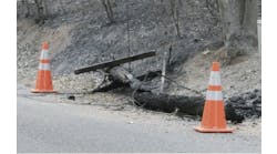
While splitter placements are easier to plan in a greenfield installation (See Figure 1.), issues such as cabinet size, termination method, and their ideal location must still be decided, just as with a brownfield installation.

Figure 1. Placing fiber optic cable in a greenfield installation.
Part of the design strategy is to decide whether a homerun, a centralized, or a distributed topology would be the most cost-effective for design. Each of these should be tailored for the specific area(s) to be served, and, in many cases, may require or justify a combination of topologies. It is important to understand the pros and cons of each topology, including the available splitter options (e.g., 1:4 x 1:8 versus 1:32) to achieve the optimum design.
Consideration should also be given to the economical selection and placement of other OSP resources, such as the feeder, distribution, and drop cables and the types of fiber required. Newer fiber structures have been designed to combat common problems in OSP installations. ITU-T G.652D low water peak single-mode fiber minimizes attenuation at the hydrogen oxide (OH) peak in the E-band, enabling possibilities for coarse wavelength division multiplexing in situations where fiber exhaust occurs. ITU-T G.657 bend-insensitive single-mode fiber is recommended to meet the tighter bend requirements of indoor installation designs.
A good physical plant design must also examine the current and future requirements of the serving area. These can vary based on bandwidth changes, growth, and migration to future PON variations. It is critical that these points are considered during the design process.
Designers and planners developing designs for FTTx networks must explore multiple types of field configurations using general engineering guidelines. The design will depend on the type of subscribers and business users, route diversity and protection, and access to the existing cable plant. Whether the site is a greenfield or brownfield also may dictate if the placement technique(s) and locations are aerial, direct buried, and/or ducted. Fiber-to-the-building designs have their own challenges based on the building’s use, age, height, and tenants, as well as the availability of internal risers for access from the OSP to the inside plant.
It is also important to note that business locations such as multiple tenant units will require more symmetrical bandwidth than residential units, which tend to require asymmetrical bandwidth. In some cases, a blend of both symmetrical and asymmetrical may be required.
When designing in The Last Mile, the locations for the distribution and drop cables must be determined. Alleys, aerial plants, curbside selection, the number of drops, and splicing and terminations are all part of the OSP design strategy.
Proper network design should be based on established fundamental fiber planning principles, should have specified design benchmarks, and should consider legacy OSP infrastructure. (See Figure 2.) This must be done with an understanding of how point-to-multipoint PON systems can adapt to growth and migration to higher-speed systems in the future while still coexisting with legacy PON systems. One benefit most designers have is a host of standards that define the components used in FTTx systems. Within the protocol standards, physical plant specifications and their values simplify the development of bid proposals and purchasing requirements.
In summary, adhere to engineering guidelines through fundamental fiber planning. Develop a fundamental plan and detail design drawings to build the network. Use existing standards to define the attenuation values required for the type of system to be installed. Determine the best solution for your design by understanding the available options for PON systems. Work out the cost issues and impacts for each design. Identify operational issues and flexibility for growth in the design process.
Visit www.iseexpo.com and sign up for:
TESTING AND TROUBLESHOOTING FTTX NETWORKS
Presented by Larry Johnson at ISE EXPO 2016
September 20, 2016 1:00 PM – 5:00 PM
Earn: BICSI – 4 CEC’s and ETA – 4 CEC’s
Save
Save
Save
Save