


7 Tips for Safety and Reliability:
Whether we are discussing a data center, a 9-1-1 facility, or even a commercial user like a hotel, data processing loads and sensitive equipment are a vital portion of the end use, and downtime of that equipment is expensive or disastrous. That is why designing or retrofitting for power quality considerations is often very inexpensive compared to the alternatives, and is considerably cheaper when introduced at the start of construction.
The first fact that must be considered is that the vast majority of power quality problems in a building originate within the building. As a result, the IEEE, LPI, and similar organizations have issued design guidelines and recommended practices that are known to greatly reduce, if not eliminate, the incidence and severity of power quality related problems. The National Electrical Code® (NEC) and similar documents are not power quality design guides.
In many cases, simply inexpensive techniques can help prevent or mitigate problems, especially when installed during construction or during a major building renovation.
Why Ground?
Here are 2 examples that illustrate the importance of grounding:
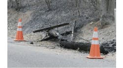
Example A: Suncoast Schools Federal Credit Union operated a data center controlling the ATM network of the bank. Lightning struck the service feeders of the center one night, blowing the electric meter off the outside wall. (See Figure 1.)

Figure 1. Meter pan (right) was destroyed by lightning and completely blown off the wall.
The bank did not experience downtime or equipment damage because it recognized the value of proper grounding. Suncoast had installed a system with 7 layers of surge protection, and connected it to an exterior grounding system with less than 5 ohms resistance to earth. As a result, lightning went into the earth, bypassing the building and its equipment, which represented a more resistive path.
In designing a lightning protection system, imagine a 150-foot radius ball rolling along the outer surface of a structure. The accepted theory is that every point under that ball is protected, while every point within the 150-foot radius is vulnerable (See Figure 2.)

Figure 2. Wherever the rolling ball touches is vulnerable. Areas in the shadow of the ball are generally protected.
Example B: The photo in Figure 3 is an actual list of circuit breakers in a panel of a facility housing 5 radio stations in Florida. Notice that the parking lot lights and elevator motor are on the same panel as the sensitive loads like the fire alarm. Should the parking lot poles suffer a lightning hit, the electronics throughout the building are in jeopardy. Sensitive loads should always be on a separate panel, isolated from motors and non-sensitive loads.

Figure 3. Motor loads, parking lot stanchions, air conditioners on same panel as fire alarm.
Make the Right Choices
The NEC allows for the use of metallic conduit as a grounding path. While metal conduit does act as a shield against radio frequencies (RF), it’s critical to know that the joints are tightened correctly and not corroded. Consider the hallway in Figure 4 which is located in a data center. Would you accept a joint in the current path every 10 feet in this run? A best practice is to always use a full-size grounding conductor, at least as large as the phase conductors.
Installers sometimes request a so-called "clean ground" for their equipment, in the mistaken belief that their equipment need not be connected to other equipment within the environment. This practice is dangerous and illegal.

Figure 4. Conduit is a questionable ground path for these circuits in a data center.
The practice establishes multiple paths to ground, thus using the earth as a conductor. This violates the NEC code. Also, by having separate grounds, a potential shock hazard may be created between adjacent equipment. Remember that all equipment must be connected to one common grounding system. (See Figure 5.)
So-called "clean grounds" are illegal and can represent a safety hazard. Adjacent pieces of equipment may be at different voltages if the earth is used as a conductor.
In a usual circuit design, the ground conductor is connected to the box housing the electrical device, plus every panel along the path back to the service. It can be contaminated by noise on the ground conductors of adjacent circuits, possibly non-sensitive loads.

Figure 5. Note that the isolated ground (IG) is located on the insulated bus, and extends all the way from the sensitive equipment back to the service point, not electrically intermingling with other circuits along the way.
A much better idea is an isolated (sometimes called insulated) ground. In this arrangement, a ground conductor is completely separate and isolated from any adjacent loads all the way back to the point of service.
An example of a good installation is by a data center owned and operated by the Markley Group in downtown Boston. The techniques are suited to any facility housing sensitive equipment, not solely data centers.
There are dual step-down services throughout the building. Two feeds from the utility, feeding a pair of substations rated 5 MVA each, housing three-step down transformers each. There are 2 distribution systems throughout. An "A" and "B" circuit are then carried to each piece of equipment. Branch circuits are at least 1 size larger than required by the NEC to limit voltage drop. Copper is used for all wiring. Each computer room has its own grounding conductor (never the conduit) to a master ground bar located in the sub-basement as shown in Figure 6. Loads are never mixed. Conduits are not shared with other circuits; each circuit is in its own conduit.

Figure 6. Master ground bus located in the sub-basement. Note that each conduit is labeled as to source.
7 Techniques to Help
Technique 1: Separation of Sensitive Electronic Loads from Other Equipment
Power-sensitive equipment from separate dedicated branch circuits emanating from separate panel boards, fed from separate feeders back to the main service entrance. The neutrals and grounding conductors need to be kept separate also. Do not mix sensitive equipment with standard loads, motor loads, or outdoor loads.
Technique 2: Limited Number of Outlets per Circuit
3 to 6 outlets per circuit maximum is recommended instead of the 13 allowed by code on a 20-amp circuit. This will minimize the number and variety of sensitive equipment sharing circuitry, tend to reduce voltage drop, decrease the chance for interaction, and leave some room for later growth or equipment changes.
Technique 3: Conduit as a Ground Path
Metal conduit, properly grounded, provides shielding of the conductors from RF energy. However, do not omit the grounding conductor (green insulated copper wire), irrespective of the conduit material. It is needed for safety, as well as assurance of a continuous, low impedance path to ground. The grounding conductor should be at least as large as the phase conductors, and is run inside the metal conduit, not outside.
Technique 4: Voltage Drop
Although the NEC allows up to a 5% voltage drop on the combined branch and feeder circuits, recommended practice is to design for no more than a 3% voltage drop at full load on the combined circuits feeding sensitive equipment. That means conductor gages should often be larger than required as code minimums. But a side benefit of larger conductor gage is that larger conductors frequently save enough energy, due to their lower resistance, to compensate for higher initial cost, with a short payback.
Technique 5: Conductor Material
The chances of problematic connections and corrosion are decreased with the use of copper conductors. Special installation precautions are not needed and maintenance requirements are reduced when using copper. Special corrosion inhibitors are not needed. Because of its superior connectability, there is less risk of a power quality-related failure.
Technique 6: Ground Rings
A buried exterior ground ring is a technique to help achieve low impedance from the building’s grounding system to the earth itself, and a convenient means to connect various grounds leading from the building. A ground ring combined with deep-earth ground electrodes (see Technique 7) provides the best system
Technique 7: Depth of Grounding
Where there is insufficient real estate to work with, or under conditions of unusually high ground resistivity, deep grounds may be required. Long copper pipe-type ground rods, sometimes tens or hundreds of feet long, in bored holes, are not uncommon in rare cases.
Lightning
The purpose of a lightning protection system is to provide a low-impedance, easy path for the lightning energy to flow; maximizing current; and, conversely, for the equipment to represent a high impedance path, minimizing current.
The use of the building framing steel as a down conductor introduces the lightning energy directly to the interior of the building, where it can damage the data or equipment, or couple to the electrical wiring. Separate copper conductors are recommended as down conductors.
Lightning systems and surge protection devices must be connected to a low-impedance ground electrode system to operate. The grounding resistance should be checked upon installation, and checked again periodically, depending on experience encountered, annually or semiannually. 5 ohms to earth or less is recommended by IEEE and others.
Conclusions
By following the recommendations outlined above, the chances of power-quality problems are minimized. However, this article gives only a broad overview of some widely-employed techniques for improving power quality. It is by no means a complete reference on the subject. Remember, codes are minimums, sometimes inadequate, and one step ahead of illegal practices. Exceeding code minimum is often recommended.
In cases where power quality problems are encountered in an existing facility, a careful study will be necessary to determine the best course of action. Solutions may be as simple as moving some loads between branch circuits, some minor rewiring, or additional branch circuits. In difficult cases, professional engineering assistance is recommended.
Photos courtesy of Copper Development Association. (www.copper.org)
Save
Save