Best Testing Practices for Next-Gen Gigabit Deployment

PAM-4 Specific Strategies
Growing demands for instant data access continues to drive Ethernet transmission innovation. After implementation of 100G Ethernet, achieving 400G Ethernet represents a significant and disruptive step. Technological advances towards achieving greater Ethernet speed presents two design possibilities, NRZ and PAM-4 (Pulse Amplitude Modulation, 4-level). NRZ (Non-Return-to-Zero) uses a currently available technology and will continue a linear evolution from 100G (25/28G, 4 lanes) to 400G (56G, 8 lanes).
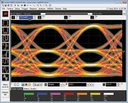
Non-linearity – amplitude compression in lower eyes.
Heading for a data rate of 400 Gb/s though, the NRZ concept is facing limitations: with shorter unit intervals and closing eyes, triggering becomes more problematic. Channel loss and reflections (noise) at increased data rates are difficult to handle for forward error correction (FEC).
PAM-4 Design and Measurement Challenges
PAM-4 from a time domain perspective has four digital amplitude levels. PAM-4 has an advantage over NRZ in that for each level ("symbol") there are two bits of information providing twice as much throughput for the same Baud rate. From a frequency domain perspective, PAM-4 requires half the bandwidth of that of NRZ. In the PAM-4 there are 3 vertical eyes created by the 4 levels. Unlike NRZ, where the decision level is fixed to 0 V for a differential signal, the 3 slicer levels used by a PAM-4 receiver can be adaptive, or time varying.
Newly developed technology is required to accomplish implementation of PAM-4 components and serial links with more complex system test setups. PAM-4 technical challenges include a shift from saturating output stages to linear IO behavior in order to achieve multiple levels. New chip designs face the challenge of managing the growing size of the integrated circuits (ICs) supporting PAM-4.
Three design and test challenges concerns include:
1. Clock Recovery. Finite rise time acting on different transition amplitudes creates inherent inter symbol interference (ISI) and makes clock recovery more difficult. Transition time of the PAM-4 data signal can create significant horizontal eye closure due to switching jitter. Transition qualified phase detectors are needed to look at analog levels for clock recovery. Whether direct detection (comparators), which require a lot of power, or digitizing ADCs, which are expensive, are used is still to be determined.
2. Decision Feedback Equalization (DFE). DFE is used to calculate a correction value that is added to the logical decision threshold and results in the vertical threshold shifting so new logical decisions can be made on the waveform based upon the new equalized threshold level. The technology required to manage DFE for PAM-4 multi-levels is still to be determined.
3. Loss of Signal to Noise Ratio (SNR). The PAM-4 signal has 1/3 the amplitude of that of a similar NRZ signal (SNR loss of ~9.5 dB) due to level spacing and is more susceptible to noise. However, it is possible that the lower PAM-4 insertion loss compensates for the 9.5dB loss in SNR due to reduced signal amplitude in PAM-4 signaling.
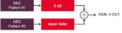
PAM-4 pattern generation utilizing a BERT.
PAM-4 Simulation and Test
Typical PAM-4 communications system configurations for transmitter (TX), channel, and receiver (RX) can be varied. New considerations for tests and end-to-end link simulation will be essential to verify PAM-4 compliance and ensure interoperability.
Test probe or fixture interference introduce additional requirements at these data rates. Random noise for example, can be induced from the device transmitter and intrinsic random noise can have its origin from an oscilloscope. It is important to be able to quantify them so they can be removed or de-embedded from the signal. Signal loss even in test cables at higher speeds is significant and may require de-embedding.
The effects of test fixtures usually can be minimized, but it is impossible to completely eliminate skin effect series trace loss, dielectric shunt loss and inductive or capacitive impedance discontinuities of the fixture channel. They cause signal loss and reflection, increasing at higher frequencies. These effects can be removed for example with direct measurement and de-embedding.
Direct measurement uses specialized calibration standards that are inserted into the test fixture and measured. De-embedding uses models of the test fixture and mathematically removes the fixture characteristics from the measurement. Examples of de-embedding methods include "simulation-based" and "calibration-based". The simulation-based method simulates the waveform before the fixture is fabricated. The calibration-based method is used to eliminate effects of the existing fixture.
Simulation modeling is very important, especially for PAM-4 at this stage and helps provide evaluation and performance prediction of a link design.
Measurement Solutions
Measurement and simulation challenges for PAM-4 today are clock recovery (CR), eye skew, and noise.
System testing verifies the TX/RX device works in a system under all conditions and can use oscilloscopes, BERTs, protocol analyzers, etc. Test and measurement in these early stages of PAM-4 links helps to build an understanding of the causes and mechanisms of artifacts that impair link error performance.
For the higher data rates, equalization is mandatory. Due to the increased signal rate, the channel distorts the signal at the receiver. The result can be seen using an oscilloscope: a partially or completely closed eye diagram will prevent the receiver’s ability to extract the clock and/or data. Equalization needs to be applied to re-open the eye diagram correcting for the intersymbol interference (ISI) and recover the clock or data.
Other correction methods are needed as non-linearity or amplitude compression can also alter the eye height of different transition eyes causing a linearity error due to a lower signal to noise ratio of the lower transitions.
Output Transmitter (TX) Characterization
Transmitter testing verifies that the output parameters meet or exceed the standard requirements including eye parameters and jitter measurements. Simple test patterns are defined to measure the different kinds of jitter.
Eye height, eye width, and eye skew are key parameters of transmitted PAM-4 signals and can be tested with the standard Quaternary PRBS13 Test Pattern. Level, the mean "thickness", and skew are also measured. There are 2 different types of PAM-4 receivers being considered for development; a slicer level based receiver where eye height/width are important, or an ADC based receiver where level variation in constellation form is most important. The Quaternary test pattern can be used to verify transmitter outputs for either receiver design.
Transmitter (TX) characterization can be performed by real-time or equivalent-time (sampling) oscilloscopes. As mentioned earlier, PAM-4 signals have a lower SNR than NRZ, so added noise as a result of the oscilloscope becomes an important consideration. Due to their hardware architecture, sampling oscilloscopes have an inherent noise floor that is very low compared to real-time oscilloscopes having comparable bandwidth, and as a result, will often yield the most accurate characterization of a PAM-4 signal.
Input Receiver (RX) Characterization
Input testing verifies that the receiver is able to detect correct bits along with impairments from a worst case channel. PAM-4 receivers are more susceptible to linearity and skew problems. The inherent ISI in the PAM-4 eye requires receivers to be much less sensitive to pattern dependent jitter. As PAM-4 receiver technology progresses, new types of stress impairments will need to be developed for testing the receiver inputs.
Similar to the NRZ receiver, the traditional tool for PAM-4 receiver characterization and input testing will continue to be the Bit Error Ratio Tester (BERT), which provides pattern generation and error detection. Some of the emerging 400G standards require PAM-4 devices to have integrated bit error measurement capability. These circuits provide simple link testing, but have no calibrated impairments. Thus a key focus for BERTs used for PAM-4 input testing will be on the pattern generator side. Error analyzers will continue to be offered for simpler devices which lack built-in test capability.
Different Methods for PAM-4 Pattern Generation
There are 2 approaches for generating PAM-4 patterns for receiver testing. The most common is based on traditional BERT NRZ pattern generators. Two channels of pattern aligned data streams, representing the most and least significant bits, are combined together to create the PAM-4 signal. The output representing the least significant bit (LSB) is attenuated 6 dB relative to the other output. A delay equal to the attenuation path is added in the output representing the most significant bit (MSB), and the 2 signals are summed together using an RF power divider. In practice, 2 attenuators are often used, a 10 dB and a 3 dB. The attenuation in both paths reduces the effect of reflections from mismatch in the transmission lines, which cause problems in PAM-4 systems. 10 dB is used in the LSB output, as 9 dB attenuators are not commonly available. The 1 dB error is corrected with the amplitude controls in the pattern generator outputs.
There are trade-offs between the 2 pattern generation methods. The combining outputs of NRZ BERTs described above allows long patterns, limited only by the length of user memory in the BERT. It also has potentially faster rise and fall times assuming proper selection of the attenuators and RF power divider. Faster rise times are important for using the generator as a golden transmitter emulator, but not for receiver input testing, as channels are generally used to slow the edges down even further. This approach can be expensive, as two high performance pattern generator outputs are required to generate a single channel of PAM-4 pattern.
The greatest limitation of combining two NRZ patterns is the limited types of impairments. NRZ BERTs can create many timing related stress types, but very little amplitude related stress types. A traditional NRZ BERT may have interference (amplitude noise) injection, but this will be applied evenly to all parts of the PAM-4 signal. As discussed earlier, PAM-4 receivers are sensitive to linearity and individual eye skews in the PAM-4 waveforms. These types of stress cannot be adequately generated using NRZ BERTs.
A very flexible alternative to BERT, is an arbitrary waveform generator (AWG) providing a broad variety of modulation schemes. The latest AWGs are not limited to PAM-4 signals and can generate any amplitude modulated signal such as PAM-8, coherent, OFDM, and QAM-N. They also allow emulation of a multitude of distortions. Stress types including jitter, interference, skew, linearity, and more, can be easily generated. As standards evolve, new stress types can be easily added.