
New Advances in Fiber Optics —
The fiber optic industry is transitioning between technologies on how best to transport ever increasing amounts of digital content. The use of direct detection techniques between transmitters and receivers has been the preferred method of transmission for decades, but with higher speed systems, the use of newer modulation formats, and coherent detection techniques including forward error correction (FEC) are game changers affecting those transitioning to data rates of 100 Gb/s and higher. The increased amount of photonic integrated circuits (PICs) and lower power consumption requires higher density packaging as shown by the new 400 Gb/s modules.
Traditional choices to keep up with the bandwidth demand have been to increase the data rate, add wavelengths, or add more fibers. Now a fourth option is to increase the number of cores within a 125 µm diameter fiber. So far, fibers with up to 19 cores have been manufactured by a variety of companies. But it seems like 7 appears to be the magical number at this time.
Multicore fibers were originally called "holey" fibers. Way back in 2002, I first saw a hand-drawn sketch of them at Sir David Payne’s labs in Southampton, England. Since then, the manufacturing process has changed a great deal to address issues such as terminations and fan-out kits, which are required to access each single-mode core. Fortunately, the industry has also created fusion splicers with rotation stages that allow the fiber to align the multiple cores. While we hear much about 400 Gb/s and 600 Gb/s transmission systems, most of these applications are used within data centers or for data center interconnects (DCI). Initially this is where multicore fibers may be implemented.
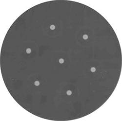
Figure 1. A 7-core multi-fiber in a 125 µm single-mode fiber. (Image courtesy of Fibercore)
Another change in the optical fiber world is a greater demand for smaller fibers. For several years, 200 µm (micron) coatings have been available. In addition, we have seen a fiber optic cable from Sumitomo with up to 6,912 fibers! A related discussion about making fiber smaller is the potential to reduce the fiber’s cladding diameter which has been consistent at 125 µm (microns) since fiber’s early days in the 1970s to 80 µm. The industry has made 80 µm fiber prior for specialty sensing applications so this isn’t a manufacturing problem. But, it would require new splicing fixtures and cleavers for fusion splicers due to the reduced diameter of the fiber. (See Figure 1.)
A final aspect relating to size and density are the new generations of fiber connectors that are significantly smaller in size. Several of the new types are the CS, for onboard optics and the SN (Senko) and the MDC (very small form factor connector) manufactured by US Conec. These connectors provide up to 3 terminations in the same space as the LC currently uses. This is critical for most module manufacturers as more complex modules with tuning capabilities are being added. These styles are designed to provide higher density options for on board optical systems, patch panels, and transceiver modules. In the case of patch panels, up to 384 of these low-profile connectors can be placed in a single RU panel and up to 15,000 for a full rack! (See Figure 2.)
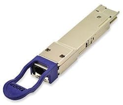
Figure 2. Smaller SN connectors and faster 400 Gb/s Pam-4 modules. (Images courtesy of Senko Advanced Products and Finisar)
Less Power Is a Good Thing
Modules also continue to decrease in size, are faster, use less power, and can provide tuning capabilities required for DWDM and WDM-PON applications. The new 400G QSFP-DD modules operate up to 400 gigabit per second transmitting 8 lanes (wavelengths) of 50 Gb/s each. The 200 Gb/s version operates with only 4 lanes. These devices all operate using coherent technology including FEC and use Integrated tunable transmitter and receiver assemblies (ITTRA).
The implementation of coherent optics solves capacity problems network providers are facing. It takes the typical ones and zeroes in a digital signal known as on-off keying (OOK) and replaces it using advanced modulation formats such as Pulse Amplitude Modulation (PAM-4) to modulate the amplitude and phase of that light, which increases the bandwidth of the transmitted signal.
Interoperability is working through the efforts of multi-service agreements (MSA), interoperability demonstrations and standardization efforts. The C-form factor pluggable (CFP-8) module having 8 lanes of 50 Gb/s using PAM-4 modulation or 16 lanes at 25 Gb/s using non return to zero (NRZ) modulation is an example of mechanical, optical, and function, all integrated into a module.
An additional issue coherent systems are addressing is the challenge of dispersion effects after the signal has been transmitted across the fiber, including compensating for CD and PMD. The use of direct detection techniques and their increased sensitivity to polarization mode dispersion (PMD) and chromatic dispersion (CD) as data rates increase forces one to address these issues when increasing the transmission levels to 40 Gb/s and higher. Even with 100 Gb/s systems with 10 wavelengths at 10 Gb/s or 4 at 25 Gb/s, each fiber characterization is critical for years to come. Already the 200 Gb/s and 400 Gb/s modules are transmitting multiple lanes at 50 Gb/s.

Figure 3. Compact Optical Spectrum Analyzer. (Image courtesy of Finisar)
Small Testing Gear
Test equipment continues to get smaller with more functions. Finisar recently demonstrated a hand-held optical spectrum analyzer which provides Optical Signal to Noise Ratio (OSNR) measurements and DWDM analysis to address high-speed needs. The push to higher speeds is creating challenges dealing with increased OSNR and optical dispersion in the outside plant which affect signal quality. (See Figure 3.)
FTTx continues to have an impact as migration from legacy 1 Gb/s (EPON) and 2.5 Gb/s (G-PON) systems to 10 Gb/s (NG-PON1) and 40 Gb/s NG-PON2 (aka WDM-PON) requires testing at different wavelengths, and in the case of WDM-PON very specific wavelengths with tighter spectral channels. Viavi’s new OLP-87 is designed to address the physical testing requirements of WDM-PON testing.
The role of the OTDR is changing as well. System manufacturers now offer OTDRs integrated into their transmission equipment providing immediate alarm functions. They are also provided on SFP modules which provide a quick troubleshooting analysis. While not replacing the traditional OTDR, it does provide immediate alarming while the traditional OTDR would be used for detail investigations and restoration measurements.
Change Is the Constant
5G networks, data center interconnects, long-haul transmission, and dense wavelength division multiplexing with up to 190 wavelengths over a single fiber, continue to meet current demands. That said, even 400 Gb/s systems will be surpassed next year by the proposed 600 Gb/s systems being touted. Already test equipment is manufactured to handle component and system testing at these higher data rates.
Smaller size, less power, faster, tunable components, new test equipment and holey fibers, oh my!
About the Author