
TAP Into FTTH for the Underserved —
Bringing broadband service to rural and underserved, exurban areas can pose unique challenges to providers. Deployments must cover great distances to reach just a few homes. Rural areas have higher costs per home passed, and require high subscriber take rates to make fiber deployments economically possible.
That’s why providers must continue to explore alternative FTTx deployment solutions. One of these network architecture options is to create or expand rural fiber-to-the-home (FTTH) networks via a tap FTTH network architecture. In a tap network, a fiber cable is deployed throughout a service area, and fiber optic taps divert optical signals to subscribers.
It’s a simple process: the cable is opened, and one of the fibers inside is carefully cut. A fiber optic tap is spliced into the line, which siphons off a portion of the signal for a subscriber. The tap allows the signal to continue down the line to the next home or business, where the process is repeated. Multiple taps can be spliced onto the line until the signal is exhausted — usually at 32 subscribers. At this point, another fiber in the cable is cut, and the process continues.

InvisiLight® Solution for Deploying Fiber
April 2, 2022
Go to Market Faster. Speed up Network Deployment
April 2, 2022
Episode 10: Fiber Optic Closure Specs Explained…
April 1, 2022
Food for Thought from Our 2022 ICT Visionaries
April 1, 2022A tap network design is quite different from the design of a traditional "centralized" FTTH network, which typically uses splitters installed in a cabinet configuration to distribute data to subscribers. In this splitter-based architecture, a fiber optic feeder line runs from the central office or head-end location to a cabinet in the street or service area. The feeder line terminates on an optical splitter in the cabinet, which distributes the signal to subscribers with additional fibers. This hub-and-spoke design gives providers great flexibility, as the cabinets allow easy management of both fiber connections and central office equipment, and can also be in proximity to remote central office equipment. (See Figures 1 and 2.)
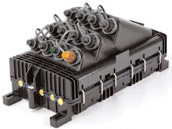
Figure 1. A traditional, centralized, FTTH network architecture (top), compared to a distributed TAP network architecture. (See Figure 2 below.)
Figure 2. Rural fiber distribution TAP architecture: A more efficient approach for deploying a future-focused FTTH network.
Difficult Topography
Of course, network architecture is a crucial decision for providers embarking on rural installations. These deployments can cover great distances of sparsely-populated terrain, with just 3 or 4 homes per kilometer. Land can be mountainous, forested, or desert, with little existing infrastructure. Providers need solutions with design simplicity, to keep labor and equipment costs as low as possible.
In comparison, a 256-subscriber deployment, tap architecture needs a minimum of 8fibers. Two 4-fiber cables are run directly into the serving area, without the need of a cabinet to house splitters and connections. Cable savings would depend upon the length of the runs to the actual drop points; but, since 4-fiber cable costs much less than 72-fiber cable, savings could be significant. Tapped architecture also avoids the need for an equipment cabinet, splitters, mounting pad, and cabinet installation labor.
The biggest difference between tap network and splitter-based architectures is cabling requirements. For a deployment serving 256 subscribers, the minimum number of fibers required in the splitter-based architecture is 256. These 256 fibers run in several smaller cables from the equipment cabinet. The cabinet is necessary to house the eight 1×32 splitter components, which route optical signals to subscribers, as well as permit fiber access. (See Figures 3 and 4.)
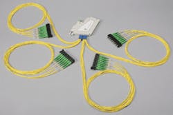
Figure 3. 1×32 splitter.
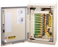
Figure 4. FDH 3000 cabinet.
Taper-Splicing
A common practice in a splitter-based approach is for a 72-fiber cable to be initially used in the serving area. Once 24 of the fibers are used, it’s cost-effective to splice the larger cable to a smaller 48-fiber cable; this is called taper-splicing. Here, tap architecture enjoys another cost savings. Because the commonly used 4-fiber cable is so small, it does not need to be taper spliced. Tap architecture eliminates the cost of splicing the larger fiber cable to the smaller fiber cable, as well as the cost to install a splice closure.
Tap architecture commonly uses 4-fiber cables, compared to the 72- or 48-fiber cables used in splitter architecture, which creates considerable savings in splicing and material labor. The number of splices required is further reduced because tap architecture requires no splitters at the entrance to the service area. In a typical tap deployment, just 2 splices will be necessary for each 2 to 8 homes: 1 for the input to the module, and 1 for the through-leg. This compares to as many as 72 splices required with a centralized architecture.
Operators can further reduce the need for splicing by using an optical terminal enclosure, or OTE, equipped with preconnectorized adapters. These fiber enclosures eliminate the need for drop cable splices, as technicians can simply plug preterminated drop cables into ports on the outside of the terminal. Because splices at residences and businesses are eliminated, this type of OTE will save even more labor time.
Additional Benefits
Two additional benefits to deploying tap network architecture include:
Benefit 1. In most deployments, a special map must be produced to chart splice input and output locations, and to indicate which fibers are connected. This is especially true with a splitter-based architecture, as technicians need to keep careful track of which fibers are joined when working with 72-fiber cables. This information must also be created for each taper and branch point in the distribution network, as well as for splitters in serving area cabinets. Splice maps can add significant cost to system designs, as a typical service area could have hundreds of splices, and maps must be maintained and updated to show any field or customer changes.
In tap architecture, no splice map is needed, as only a single fiber is used on each run, and the indication of which fiber is spliced is readily done on the standard design map. This simplicity helps avoid both expensive connection errors and the production time for the splice map.
Benefit 2. Troubleshooting is also efficient in tap architecture, as technicians can easily check connections through fiber-optic taps with an optical time domain reflectometer, or OTDR. In splitter architecture, the OTDR signal can’t pass through the distributed splitters, making it more difficult to check connections.
Future Possibilities
Some operators believe that, compared to splitter architecture, tap architecture networks are difficult to expand. While it’s true tap systems are often designed with minimal fiber use, to save as much upfront cost as possible designers can use a 1:2 split at launch to increase optic use efficiency. If expansion is required later, this 1:2 split can be removed to add capacity, and additional fiber optic taps added to change to a higher port count.
Like this Article?
Subscribe to ISE magazine and start receiving your FREE monthly copy today!
In another expansion strategy, many operators purchase dark fibers along with the initial 4-fiber cables, as the economics are best with a full buffer tube of 12 fibers. The cable size doesn’t change, and the additional dark fibers provide the highest utility of all solutions, with each fiber good for another 32 homes.
While several fiber architectures have been developed to support FTTH deployments, tap network architecture is a strong option for telecom providers looking to build out their rural broadband networks.
About the Author