Transitioning From 10 Gb/s to 40 Gb/s —
With the increasing trend to higher bit-rates, an uncommon type of optical dispersion has emerged. Called polarization-mode dispersion (PMD), it has the potential to become a network-killer in systems operating beyond 10 Gigabits per second. Thus, the understanding and mitigation of PMD is extremely important to anyone who works with high bit-rate fiber systems.
In this article we address what PMD is, its causes, and why fiber characterization of chromatic dispersion (CD) and PMD testing is important to obtain the best signal quality for those upgrading transmission speeds up to 40 Gb/s. We also address what is needed for 100 Gb/s transmission systems using coherent detection and forward error correction (FEC).
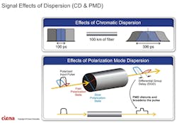
Recently we featured 2 articles on chromatic dispersion (CD): "A Colorful Problem" (See September 2018 issue: https://isemag.com/2018/09/a-colorful-problem/), and "Controlling Chromatic Dispersion" (See October 2018 issue: https://isemag.com/2018/10/chromatic-dispersion-100gb-s-problems-solutions/). Both of these are helpful to understand the relationship of optical dispersion on single-mode systems and to address and understand fiber characterization (FC), including this article’s focus on PMD. (See Figure 1.)
Figure 1. (Courtesy of Cienna)
Polarization Mode Dispersion (PMD) like chromatic dispersion causes optical pulses to spread which limits the effective bandwidth of the span. PMD mostly affects systems at transmission rates between 10 Gb/s and 40 Gb/s. The problem with PMD is that it is random as it is directly affected by thermal changes and vibrations.
To understand PMD, a little background on theory helps. Like all electromagnetic radiation, light waves have an electrical component and a magnetic component that oscillate perpendicular to one another and to the direction the light wave is travelling. The polarization direction is defined as the alignment of the electrical field. The light wave has its electrical field in the vertical direction and is said to be vertically polarized. If the electric field is horizontal, the light is horizontally polarized. If the field direction rotates as the wave travels, the light is said to be elliptically polarized or circularly polarized.
InvisiLight® Solution for Deploying Fiber
April 2, 2022Go to Market Faster. Speed up Network Deployment
April 2, 2022Episode 10: Fiber Optic Closure Specs Explained…
April 1, 2022Food for Thought from Our 2022 ICT Visionaries
April 1, 2022Unpolarized light consists of a random jumble of all states of polarization. Some sources emit polarized light and some do not. Regardless of the source, most single-mode fibers support only two perpendicular modes of polarization of the transmitted signal, often called the fast axis and the slow axis. Different polarization states (SOP) vary in speed (slow vs. fast axis causing pulse spreading over the length of the fiber.
In a perfectly symmetrical fiber, the 2 polarization modes travel at the same speed, behave as a single mode, and there is no problem. However, fibers are not perfect, and slight differences in core and mode field diameter diameters and ovality along the fiber span causes one of the modes to propagate slower than the other, resulting in pulse spreading.
In addition, when a fiber is squeezed, bent, or stressed, the glass temporarily exhibits 2 refractive indices, a property called birefringence. Birefringence greatly increases PMD effects. PMD can be hard to mitigate because the effect is random and can fluctuate with environmental conditions. Common examples include thermal stresses, and the random vibration present near railroad tracks.
PMD has not been a significant effect in shorter spans at bit rates up to 10 Gigabits per second. But with the tight bit period of 40 and 100 Gigabit systems and closer spaced channels in DWDM systems, the mitigation of PMD and chromatic dispersion (CD) effects is essential. PMD compensation is quite complex, and is most commonly done in the electrical domain at the detector or receiver location.
Testing Matters
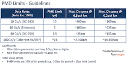
To ensure that existing fiber spans can handle 40 Gigabit traffic and beyond, it is necessary to perform PMD tests. A number of manufacturers offer test equipment for this purpose. Older fibers before the recognized effects of PMD were identified need to be tested to confirm their values for operation from 10 up to 40 Gigabits per second. The objective is to make sure the PMD measurements will allow system operation at the desired bit error rate. (See Figure 2.)
Figure 2. (Courtesy of FiberInsight)
Since the late 1990s, the transport capacities of long haul and ultra-long haul fiber optic systems have been significantly increased by the introduction of erbium doped fiber amplifiers (EDFA), Raman optical amplifiers, dense wavelength division multiplexing (DWDM), and dispersion compensation technologies. In the past, simple on/off keying (OOK) modulation formats in conjunction with direct detection methods have been sufficient to provide data rates up to 10 Gigabits per second per channel.
To extend the reach and data capacity beyond these legacy systems, several technological advancements are occurring which mitigate the effects of PMD at 100 Gb/s and higher. The first is the adoption of a number of advanced modulation schemes based on phase shift keying (PSK). Instead of modulating a light source by switching it on and off, known as on/off keying (OOK), PSK techniques convey data by modulating the phase of the optical carrier. Conventional PSK uses a finite number of phases, each assigned a unique pattern of binary digits, or symbol. The demodulator, which is designed specifically for the symbol-set used by the modulator, determines the phase of the received signal and maps it back to the symbol it represents, thus recovering the original data.
This requires the receiver to be able to compare the phase of the received signal to a reference signal generated by a local laser oscillator. Because of this, the system is called coherent. As transmission speeds increase, so does the occurrence of transmission errors. Forward error correction (FEC), is a technique that allows for nearly perfect data transmission accuracy, even when faced with a noisy transmission channel. FEC adds redundant data to messages, which allows the receiver to detect and correct errors within certain limits. This results in a lower receiver-end optical signal to noise ratio (OSNR), at the cost of higher bandwidth requirements due to the error correction data added to the signal.
Most 100 Gb/s systems use coherent detection and incorporate electronic dispersion compensation (EDC) technologies for both chromatic and polarization mode dispersion. This mitigates the effects of PMD but all fibers should be fiber characterization (FC) tested to establish baseline measurements and to measure the total PMD value in the link. This will also define length limitations as well as whether the fiber has poor PMD values or was installed incorrectly. Random events such as changing temperature cycles, wind, and vibrations, can change these values. Full FC testing includes optical attenuation, bi-directional OTDR testing, component and optical return loss (ORL) testing.
Testing for PMD can use the Fixed Analyzer Method used primarily for metro, regional, long haul, and submarine, installations and can also test through amplifiers. SOP sampling analysis (SSA) testing technique is primarily used for metro/mesh networks and is a one-ended test. But requires a second technician at the far end to clean connectors and move an optical reflector as needed for the fiber under test.
The goal of these tests is to obtain a total PMD value (ps) to determine the total PMD and averaged differential group delay (DGD) in 10 G b/s + links which use traditional direct detection techniques.
Another measurement to confirm is the PMD coefficient (ps/√km) for the specific fiber manufacturer and type. Poor installation practices or bad PMD fiber can be identified during PMD and CD testing.
Fiber optic standards have established specifications for fibers which can identify fibers with poor fiber transmission and physical characteristics.
In a presentation at a recent ISE EXPO, Tim Yount, Founder of Fiber Insight, a company that specializes in fiber characterization stated, "Important consideration to consider for service providers and users include thinking long term and addressing high-speed transmission systems. Do you know which fibers within your infrastructure will only ever carry transmission with coherent detection with digital signal processing? If the answer is yes, then those fibers should be tagged, and while you do not need to worry about CD, and while the effects of PMD are mitigated for much greater levels, it is still present and electronic dispersion compensation (EDC) is not unlimited. By identifying each fiber’s characteristics, specific future fiber allocation can be assigned for the best transmission quality."
Summary
It is critical that anyone transitioning from legacy SONET/SDH systems to new coherent transmission systems understand the impact that PMD has between 10 Gb/s and 40 Gb/s operation and its optical dispersion impact.
Like this Article?
Subscribe to ISE magazine and start receiving your FREE monthly copy today!
There are several options to PMD testing. Tier 1 test equipment manufacturers provide PMD and CD test sets for sale, test equipment rental companies lease the equipment, and there are qualified contractors who specialize in fiber characterization testing, as well.
Remember: specialty fiber characterization training is required to perform the testing, and to analyze and document the results.
About the Author


