Overlaying Mid-Band Spectrum Backhaul/Fronthaul Onto HFC
Cable 10G and Wireless 5G seem like completely separate technologies, but service providers can evolve by combining them in their networks. 5G runs over several different frequency bands, and each band has its own features. C-band and CBRS (Citizens Broadband Radio Service) frequencies offer some new mid-band spectrum that could be a mainstay of 5G in the future.
5G’s reach covers a significant number of mobile users with data rates above 1 Gigabit, but its deployments typically require many more cell sites than current 4G LTE macro cells, and those cell sites will be closer together. This situation presents an opportunity for MSOs to leverage their existing HFC infrastructure for providing both backhaul and power to those new cell sites.
Small Cell Deployments
5G services require much more densely located antennas. For cable operators, the most enticing 5G use case that takes advantage of their HFC infrastructure is the small cell deployment. Perhaps the 2 most obvious applications would be 1) strand mounted small cells (on aerial coaxial plant) and 2) pole-mounted small cells (mounted on streetlights). Streetlights may be the best or only option for underground plants in some cases. Streetlights also have an advantage over strand mounts as they are at a higher elevation (i.e., 45’ vs. 30’), which enhances the reach of the antenna.
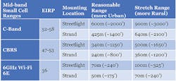
Figure 1 provides some small cell range estimates for C-Band, CBRS and WiFi 6E. The coverage is impacted by the transmit power, which varies quite a bit between technologies. WiFi 6E could be also seen at a disadvantage as it is using the 6GHz band, which has higher path losses than the 3.5 to 4.0 GHz bands used by CBRS and C-Band. Rural areas tend to have fewer obstructions and typically have farther reach.
Mapping 5G Mid-Band Small Cells To HFC
The 3GPP’s 5G-R RAN2 specification included several functional split options. A discussion is detailed in the white paper "A Survey of the Functional Splits Proposed for 5G Mobile Crosshaul Networks" (1). Today, most 5G industry focus is on 1 of 2 options:
- Option 2 ("Midhaul"): a high-level centralized unit (CU) and a distributed unit (DU) split which separates control and user planes. The DU and remote radio unit (RRU) might be combined into a single entity as a self-contained access point.
- Option 7.2 Cat A ("Fronthaul"): a low-level split that allows for high reliability and low latency communications and near-edge deployment. This split takes place between the Hi-PHY (Physical Layer) and Low-PHY. In this split, only the Low-PHY and RF functions are in the access point.
Small cell bandwidth capacity requirements are greatly reduced for Option 2 Midhaul. Option 7.2 Cat A Fronthaul might require a 10 Gbps fiber link while Option 2 Midhaul can be carried over cable using DOCSIS 3.1 technology.
In the paper Overlaying Mid-Band Spectrum Backhaul/Fronthaul onto HFC – A Symbiotic Convergence of Cable & Wireless from SCTE Cable-Tec Expo 2021, I present some detailed case studies on mapping 5G Mid-band small cells to HFC. For N+3 plant and a wide range of homes-passed densities (i.e., 37 to 274 HP/mile), a single CBRS small cell that is co-located with the fiber node is sufficient to cover most of the homes. These small cells could leverage either midhaul or fronthaul. For those nodes that need additional coverage, only 1 or 2 small cells per DOCSIS networks using Option 2 mid-haul are needed.
Operators with larger HFC cascades (e.g., N+5, N+6) are expected to need additional small cells to achieve their coverage. Another case study from the article Overlaying Mid-Band Spectrum Backhaul/Fronthaul onto HFC looks at a much larger North American metro suburban area (2). It considers a 3.5 square mile area that covered 9 nodes that were mostly N+6. Overall density was about 100 homes passed (HP) per mile while individual nodes varied from 75 to 165 HP/mile.
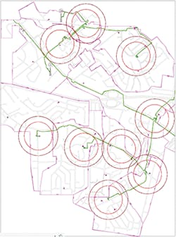
Figure 2 displays 9 CBRS small cells located next to or near the fiber nodes. These small cells provide access to power and fiber backhaul, allowing an Option 7.2x fronthaul interface. Figure 2 shows less than half of the area has coverage, even with the extended 350m streetlight range. If the operator’s goal is just to off-load some mobile data onto its network, this coverage might be good enough.
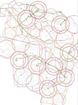
Figure 3 shows area coverage as filled with coax strand-mount CBRS small cells. These small cells would use DOCSIS 3.1 for midhaul. That case would require 23 additional coax-based small cells to get reasonably complete coverage. Note that using streetlight mounting increases the coverage area to 350-500m and might eliminate a third of these coax-connected cells.
Our HFC design team did a N+0 upgrade design for the study area. (3) This upgrade pushes fiber much deeper. Total fiber mileage for N+0 upgrade increases from 8.55 miles to 24.8 miles. Note in the N+0 design that there are now 110 fiber nodes compared to a total of 32 small cells for this area.
In general, N+0 upgrades tend to be relatively expensive because of the amount of fiber being pulled. As shown, N+0 designs also push the fiber much deeper than is needed for CBRS small cell coverage. The study estimated that an N+2 upgrade might have fiber node placements that align nicely with CBRS small cell placements.
These case studies show that N+2/N+3 might be an optimal HFC design target for operators thinking of 5G mid-band convergence. As time progresses and bandwidth needs continue to rise, an operator might want to migrate from a DOCSIS-based backhaul to a fiber backhaul. So, the operator might consider how it will eventually pull fiber to these small cells on the HFC coax plant as part of their overall fiber deeper strategy.
Potential Mid-Band Opportunities
CBRS/C-Band small cell reach covers a significant number of mobile users with substantial data rates. But its deployments need many more cell sites then current LTE macro cells. This should present an opportunity for MSOs to leverage their existing HFC infrastructure for both backhaul and power.
For rural locations, MNOs have typically used low-band frequencies to maximize the distances between their macro tower base stations. This type of spacing may not be suitable for C-Band delivery from the tower to reach the entire community. As 5G bandwidth needs increase, MNOs may decide that deploying C-Band small cells is more economical than building more macro towers. Cable operators can provide the location (i.e., strand-mount) along with power and backhaul as a service to the MNO that owns the C-Band spectrum. Alternatively, cable operators might deploy their own 5G mobile network leveraging CBRS over their own infrastructure.
In rural areas, cable operators can use GAA to access the CBRS spectrum. If the MSO is acting as a virtual MNO (vMNO), it might choose to place a handful of CBRS small cells in the busiest locations as an offload strategy; or the MSO might build out the CBRS small cells across its HFC plant for more complete coverage. Note that 100 MHz of spectrum can enable impressive user equipment data rates of 2 Gbps down by 300 Mbps up.
In urban settings, 4G capacity needs have already forced the MNOs to locate macro towers much closer together. So, they will likely be in a much better position to offer C-Band from macro towers leveraging sophisticated antenna arrays and beam forming algorithms. The need for C-Band small cells is expected to be much smaller, but it may still be needed in hot spots to help reduce congestion. Therefore, the CBRS small cell will be seen as key for MSOs in urban settings. But there will potentially be many others competing to get CBRS spectrum in these settings.
Conclusion
HFC is well-suited to support a mid-band transport infrastructure as I have described. DOCSIS 3.1 mid-haul can be leveraged extensively early on in the transition to 5G to get wide coverage quickly. Dense urban areas may eventually require complex 5G antenna/MIMO systems with fiber fronthaul, which integrates nicely with an N+2 fiber deep strategy. But even with MIMO systems deployed, additional cells with DOCSIS xHaul will be needed to fill the coverage holes. In the future, DOCSIS 4.0 is estimated to enable even higher capacities at these cable cell sites.
So, even though they may seem like separate technologies, cable and Mid-band wireless (C-Band and CBRS) are much stronger when used together.
Resources And Notes
1. [LARSEN_2018] P. Larsen, et. al., A Survey of the Functional Splits Proposed for 5G Mobile Crosshaul Networks, IEEE Communications Surveys and Tutorials, 2018
2. [ULM_2021] John Ulm, Martin Zimmerman, Stuart Eastman, Zoran Maricevic, Overlaying Mid-Band Spectrum Backhaul/Fronthaul onto HFC – A Symbiotic Convergence of Cable & Wireless, SCTE Cable-Tec Expo 2021, SCTE
3. [ORAN_2020] ORAN-WG9.Transport.0-v00.12 Technical Specification, O-RAN Open Xhaul Transport Working Group 9 Xhaul Transport Requirements, O-RAN Alliance, 2020
For more information, visit https://www.commscope.com/.


