Cloud-RAN Deployment With CPRI Fronthaul Technology
The increasing use of smart phones and tablets is fueling the demand for ever-increasing availability of higher-bandwidth mobile networks such as 4G LTE. Multiple technologies are commercially available for the delivery of higher bandwidth services. Advanced modulation schemes, more powerful and integrated antennas, and superior wireless backhaul technologies, help increase the capacity of cellular networks. This article focuses on a fiber-based fronthaul technology.
Addressing Limits
As the demand for capacity in metropolitan areas has grown, macro cells have reached their limits in terms of the number of locations and/or penetration capability in indoor or densely populated locations.
2 major alternative technologies try to address these limits:
Alternative Technology #1. Small cells are one major innovation that is being currently deployed in larger volumes for capacity enhancements in hotspots in metropolitan areas. They also cover extension in rural areas and are being deployed indoors. Small cells are low-powered access nodes that include the functionality of a base station in a small enclosure. They can be mounted on rooftops and poles without a significant footprint or utility cost.
Alternative Technology #2. Using smaller nodes for hotspots can be taken a step further, which is the focus of this article. Unlike a small cell, a distributed system is deployed in which the radio units remain in the enclosure on the poles or rooftops, but the baseband processing units (BBU) are separated and removed to a location on the bottom of the structure or placed in a central office nearby. This technological advancement is enabled by technologies such as CPRI and fiber.
Fronthaul Network Deployment
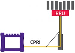
CPRI is a digitized and serial interface that was originally designed as an internal interface for radio base stations. It aims to enable independent technology evolution on both sides of the interface. (See Figure 1.)
Figure 1. A CPRI interface.
Deployment of fiber technologies inside cell sites and in access networks delivers a new CPRI use case where radio equipment (RE) can be positioned closer to antennas on tops of towers or rooftops, and radio equipment control (BBU or DU) can be located further away from the RE.
The positioning of RE (RRH or RRU) close to an antenna significantly reduces the length of coax cables for the interconnection of RRH and antennas, thereby improving the link budget and user throughput. With CPRI, the link between BBU and RRU can be extended to several miles. This opens new applications such as offloading of macro cells and distributed antenna systems (DAS). In densely populated areas, the demand for wireless Internet services may challenge the available capacity of macro cells. By positioning additional RRU in these hotspots, the wireless Internet traffic can be offloaded from macro cells.
Most DAS systems are used indoors and use coax or mixed coax/fiber media. Larger parts of the indoor systems use analog signal transmission, although an increasing number deploy digitized interfaces such as CPRI. The nodes can be arranged in star or daisy-chain topologies.
InvisiLight® Solution for Deploying Fiber
April 2, 2022Go to Market Faster. Speed up Network Deployment
April 2, 2022Episode 10: Fiber Optic Closure Specs Explained…
April 1, 2022Food for Thought from Our 2022 ICT Visionaries
April 1, 2022Using CPRI technology in combination with fiber delivers other advantages for deploying BBUs. BBUs typically need power and air-conditioning, and require a footprint that can be rare and costly in some locations. (Associated utility and leasing/purchasing costs are significant contributors to the OpEx/CapEx of cellular networks.) Fiber-based CPRI technology lets the BBU be removed to a central location such as a central office that already has telecom infrastructure.
Furthermore, by stacking BBU (BBU centralization or BBU hostelling) belonging to various RRU in one location, one can save energy, improve security without a need for IPsec-like protocols, and make the infrastructure ready for advanced LTE systems that deploy cooperative multi-point (CoMP) features.
Going one more step, the BBU hoteling can be combined with a pooling of BBU resources; this stage is known as cloud RAN (CRAN). It improves the utilization and reliability of radio access networks; it also simplifies the mobility management and reduces the number of S1 and X2 interfaces to the core network.
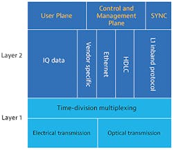
Finally, CPRI combined with wavelength division multiplexing (WDM) delivers another benefit for radio access networks: a larger number of RRU can share fiber with other services in access/aggregation networks or, alternatively, multiple wireless operators can share fiber in RAN (RAN sharing). (See Figure 2.)
Figure 2. CPRI protocol layers.
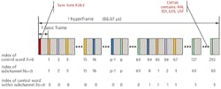
CPRI signals are composed of basic frames (BF) that are grouped in hyperframes as shown in Figure 3. A basic frame contains 16 words. The length of the word ranges between 8 and 128 bits, and is dependent on the CPRI line rate; the higher the line rate, the longer the word. Before physical transmission of the words, they go through an 8b/10b or 64/66b encoding process according to the Ethernet IEEE 802.3 standard.
Figure 3. CPRI frame structure.
The first word is a control word. The remaining 15 words are used for user plane data. The user plane carries the data (in-phase/quadrature [IQ]) in raw format. A group of 256 consecutive BF represents a hyperframe. A hyperframe starts with a sync bytes (K28.5 byte) control word.
Other control words are used for:
• L1 inband protocol
• C&M channel
• Sync and timing mode
• Link delay accuracy and cable delay calibration
• Link maintenance of physical layer
Next, let’s take a look at some of these control words that are useful for field deployment. Link maintenance bytes deserve special attention.
CPRI protocol defines these alarms:
• Loss of signal (LOS)
• Loss of frame (LOF)
• Remote alarm indication (RAI) y SAP defect indication (SDI)
For each of these alarms, a bit is reserved in the CPRI hyperframe so that far-end equipment can be notified of an alarm in near-end equipment. When near-end equipment detects an alarm, it immediately sets the respective bit. Once the alarm condition is cleared, the bit is reset.
CPRI Test Applications
RRHs are installed and commissioned in large volumes. It is extremely important to have a smooth process with no installation failures as technicians leave the site. Because of the special skills and certification needed for tower climbing, unnecessary field errors can be quite costly. Therefore, it is essential to have tools and procedures to conduct tests from the bottom of the tower. The only test interface available at the bottom of the tower is CPRI. This section details some of the test applications at the CPRI interface.
Terminating, Troubleshooting, and Turning Up
Installing RRUs includes several steps that are typically conducted in challenging working conditions on the tower. These steps include equipment installation and fiber/power/coax cable assembly. Errors in proper wiring or the configuration of equipment have severe consequences for the operation of the RRH. (See Figure 4.)
Figure 4. Terminating an RRU.
Therefore, it is recommended that technicians perform some basic tests. Starting with an inspection and validation of fiber/connectors, technicians can isolate any issues with dirty connectors and/or fiber damages. Following these tests, a CPRI test is needed in order to verify that the RRH is operational and that the correct optics such as SFPs are installed.
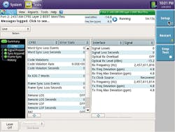
Using CPRI test equipment, basic parameters of the CPRI link are easily verified. These include signal level, frequency, frequency offset, word sync status, and word counts. The tests make sure that the RRH has the right line rate and timing, and that it is transmitting frames to the bottom of the tower.
Beyond initial installation tests for the RRH, one can also use a CPRI tester for troubleshooting problems between a BBU and an RRU. Misconfigurations and miswiring can contribute to problems in turning up a service. For example, a wrong SFP at the BBU will not work with the RRU even if the equipment is otherwise installed, wired, and configured correctly.
Using the CPRI tester in monitoring mode, both directions (up/downlink) can be monitored. Checking signal, frequency, timing mode, and word count, one can identify potential problems and their causes. Also, any present alarms (LOS, LOF, RAI, SDI) can provide valuable information on the direction and cause of an error.
Turning Up xWDM-based Fronthaul Networks
Installing xWDM-based networks requires proper planning and execution of the muxing/demuxing ports on the xDWM nodes. Wrong mapping or optics can cause RRU initiation problems. Cross wiring can lead to wrong sectors being connected to the appropriate BBU ports. A CPRI tester easily tests the transport characteristics of the individual RRU/BBU links. Beyond signal, frequency, sync, and frame count, a bit error rate test (BERT) checks the health of the links through the optics and mux/demux elements. (See Figure 5.)
Figure 5. CPRI test results.
References and Notes
This article contains excerpts from the white paper Cloud-RAN Deployment With CPRI Fronthaul Technology. You can find the white paper at https://www.viavisolutions.com/en-us/support/files/CPRI-White-Paper.pdf.
For more information, please email [email protected] and visit www.viavisolutions.com. Follow VIAVI on Twitter @ViaviSolutions.


