Covert Concealments

Ubiquitous 5G Requires Unique Small Cell Concealments —
Meeting the goal of ubiquitous 5G service means deploying about 1 million 5G nodes from the approximately 300,000 that currently exist, according to Ericsson studies.
With the density of these nodes popping up across the urban, suburban, and rural, landscapes, the newly installed equipment must be aesthetically pleasing.
Several of the gating factors in deployment of 5G are zoning considerations, permitting and acceptance by local authorities having jurisdiction (AHJs) as well as local municipalities. Typically, permits for small cell infrastructure can be processed within 60 to 90 days, depending on the type of installation and if they meet the community’s noise and aesthetics requirements. While aesthetics is subjective, cities and homeowner’s associations (HOA) generally require pole-mounted telecom equipment to be inconspicuous.
This is especially true with small cells as they are installed at street level and easily viewed by the public. While most small cell equipment is minimalistic and well-packaged on the outside, there are certain installations that may require the use of concealment systems or shroud. As an example, an installation of 5G equipment may clash in a downtown area seeking to maintain a historic look unless the hardware is somehow concealed. A concealment system consists of shroud or cover to hide or disguise the mounted network equipment associated cable and hardware.
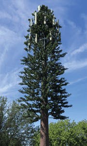
Figure 1. Camouflaged Wireless Tower
Concealments are nothing new, and, thankfully, have come a long way from camouflaged wireless towers. (See Figure 1.)
There are new concealment products that are optimized for good looks, and allow for fast site approvals and easy installation.
THE PROS of a concealment system are:
- That it greatly helps with the aesthetics of an installation, enabling an acceptable permitting process.
- It can also help reduce theft by hiding copper/RF cables and other components often targeted by thieves.
THE CONS are that if the concealment system is poorly designed or selected, the performance of the radio and antenna system can be greatly reduced.
The objective of concealment is to turn the installation as shown in Figure 2 to something more like Figure 3.
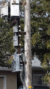
Figure 2. Crowded Installation
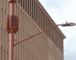
Figure 3. Clean Unobtrusive Installation
These concealment systems need to do more than just look good. These are specially engineered small cell enhancements that must be compatible with the radio and antenna designs, and must be thoroughly reviewed for structural, thermal, noise, and RF, capabilities.
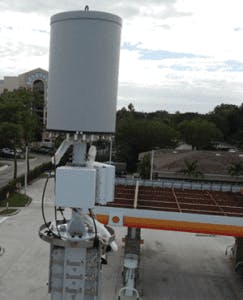
Figure 4 shows a rooftop system without a concealment system.
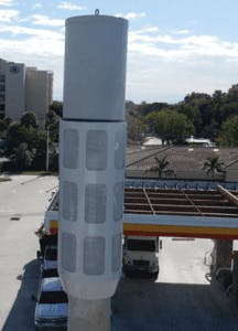
Figure 5 shows a rooftop system with a concealment system.
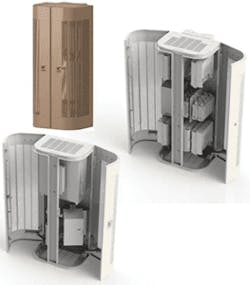
Figure 6 shows the inside of a concealment system, with radios and other equipment mounted.
Each site is unique and requires more than a cookie-cutter approach. Having the ability to provide customizable stealth concealment designs in-house allows for flexibility and speed needed for many different applications, such as roof top, wall or pole mount, or even streetlight installations.
Flexibility is key as we move from 300,000 sites to over one million sites, with over 20,000 jurisdictions requiring different solutions. States are developing laws that take into consideration the unique circumstances of their state and local environment, and establishing baseline standards like streamlined applications to access public rights-of-way, caps on costs and fees, and consistent timelines for consideration and processing of cell siting applications.
In selecting a pole mounted concealment system there are several considerations.
If possible, space inside the concealment should also be reserved for ancillary equipment such as a power supply unit (PSU), junction box, RF filters, fiber distribution box, ground bar, cabling, etc.
It is important for the concealment to blend in with the pole as much as possible. A design that is slim and long is preferred over wide and short. To cover various preferred looks, the concealment system must be able to be painted, for camouflage. Many radio equipment manufacturers do not recommend painting the radio as it may affect performance of the unit and may apply limitations to the warranty and service contract.
In looking at concealment designs, the preference is to conceal all cooling fins, front and back, but it may be necessary to leave the back fins exposed if needed to assure high temperature operation. A second option is to equip the concealment with a fan tray to maintain a suitable operating environment. To look as seamless as possible, there should be no, or minimal perforations and venting holes unless required for thermal performance or wind resistance. If perforations are required, the holes should be as small as possible to maximize concealment and also prevent intrusion by stinging insects.
Clearly, the concealment system must be able to be securely mounted to the pole and able to support expected weight of the radio plus all other support equipment. It is important to include a suitable safety factor in the calculations.
And equally as important, the concealment must allow easy access to the equipment for maintenance purposes.
MECHANICAL REQUIREMENTS
Looking at the mechanical requirements, the following should be considered.
Pole-mounted concealments should not interfere with access to or the ability to climb the pole.
The concealment should be designed to mount on a mast, pole or wall and have a mounting bracket with the following provisions:
- ½" slots for banding (hose clamps) on metal or wooden poles. NOTE: ½" anchor bands can typically support up to 1,500 lbs.
- ½" holes for through-bolts on wooden poles. NOTE: ½" machine bolts can typically support up to 5,000 lbs.
- The mounting bracket should be aluminum or steel, strong enough to safely and rigidly support the weight of the assembly and all attached equipment.
- For pole-mounted applications, the concealment should be as narrow as possible to attempt to match the profile of the pole. Typical 35-40-foot utility poles found in cities are about 10-12 inches in diameter.
- The concealment should be designed with a removable cover or hinged doors to allow maintenance personnel easy access to the equipment.
- The concealment should be large enough to conceal the equipment behind it.
- The concealment should have mounting provisions (specific pre-drilled hole patterns) for the installed equipment.
- The concealment geometry should allow space for short coaxial RF cables to be connected to radio antenna ports while providing for a drip loop where necessary without compromising the minimum allowed bend radius of the cable.
- The concealment solution should include cable holes or knockouts through the back plate for cable ingress and egress.
- The concealment should comply with Telcordia GR-1089-CORE Electromagnetic Compatibility and Electrical Safety – Generic Criteria for Network Telecommunications Equipment, Section 9 "Bonding and Grounding".
- The solution should be free of defects, such as sharp edges, that could present a safety hazard to personnel involved in the assembly, installation, use, or maintenance of the product.

InvisiLight® Solution for Deploying Fiber
April 2, 2022
Go to Market Faster. Speed up Network Deployment
April 2, 2022
Episode 10: Fiber Optic Closure Specs Explained…
April 1, 2022
Food for Thought from Our 2022 ICT Visionaries
April 1, 2022GENERAL REQUIREMENTS
In general, concealment solutions should comply with General Requirements for surface temperature, graffiti resistance, insect intrusion, exposure to high temperature, wind resistance, acoustic noise, earthquake resistance, etc., found in:
- Telcordia GR-487-CORE Generic Requirements for Electronic Equipment Cabinets
- Telcordia GR-3108-CORE Generic Requirements for Network Equipment in the Outside Plant (OSP)
- Telcordia GR-3178-CORE Generic Requirements for Wireless Transceiver Facilities
EVALUATE PROPERLY
Remember, there are potential pitfalls with concealment systems. First and foremost, the system should be evaluated properly so it does not affect the operation of the radio and antenna system. This type of analysis should examine 2 major areas: 1.) mechanical and 2.) environmental. In addition, service providers must ensure that the criteria listed earlier is included in this examination.
IN CLOSING
Use of concealment systems allow for better looking 5G systems, and help expedite the permitting process. The key to success is the selection of the right product for the radio system.
Ericsson’s Network Infrastructure & Site Solutions Team designs, extensively tests, and works with contract manufacturers, to provide concealment solutions that not only look good, but effectively mesh with the operating parameters of the wireless systems. Our team is ready to help with any installation issues that may be slowing deployments of Ericsson equipment.
For more information, please email [email protected] or visit https://www.ericsson.com/en. Follow Ericsson on Twitter @ericsson.
Like this Article?
Subscribe to ISE magazine and start receiving your FREE monthly copy today!
About the Author
 Ernie Gallo
Ernie Gallo
Principal Outside Plant and Electrical Code Consultant, NEBScore
Background • 44+ years experience in Telecom Industry • 7.5 Years Underwriters Laboratories • 33 Years Bellcore-Telcordia-Ericsson • BSEE Polytechnic University of New York Consulting Focus Areas • Electrical Safety, Electrical Protection • FCC Infrastructure Sharing During Emergencies • Outside Plant Product and Installation Standards and Audit Analytics • Industry Standards and Code Compliance – Regulatory and Safety – construction focused • Fiber to the Home – micro-trench and MDU architecture • Fiber to the Node – VDSL to the home • Wireless Products and Installation Methods • Fiber and 5G Wireless product requirements • Optical Transport Networks –Deployment Designs • Working with local Authorities Having Jurisdiction on Electrical and Fire Codes • Electrical and Fire incidents and evaluations • Expert Witness in the areas of outside plant construction and safety Industry and Project Experience Standards Work National Fire Protection Association (NFPA) • NFPA 1 Fire Code - Committee Member • NFPA 70 National Electrical Code (NEC) - Committee Member CMP1, CMP 16and Correlating Committee Member NFPA 70E -Standard for Electrical Safety in the Workplace - Committee Member • NFPA 780 Standard for the Installation of Lightning Protection - Committee Member • NFPA 855 Standard for the Installation of Energy Storage Systems - Committee Member • NFPA 75, Standard for the Protection of Information Technology Equipment - Committee Member • 2022 Committee Service Award from the Standards Council of the National Fire Protection Association (NFPA) Institute of Electrical and Electronics Engineers (IEEE) • IEEE C2 National Electrical Safety Code - Committee Member, Subcommittees SC2, SC4, SC5, and SC8 • IEEE Wire Line Subcommittee – Vice Chair • IEEE Working Group 3.6.7 Low Voltage Data, Communications and Signaling Circuit Surge Protective Devices – Chair • IEEE Working Group 3.6.10 Surge Protection of Equipment Connected to Both Low Voltage AC Power and Communication Circuits – Vice Chair • IEEE Fiber Optics Subcommittee - Committee Member Association for Telecommunications Industry Solutions (ATIS) • ATIS Board Member • ATIS Protection Engineers Group (PEG) Chair and current Advisory Board Member • ATIS STEP: Sustainability in Telecom: Energy and Protection Committee – Vice Chair • ATIS Network Power Systems (NPS) – Chair • ATIS Network Physical Protection (NPP) - Working Group Member • ATIS Network Electrical Protection (NEP) –Chair Underwriters Laboratories (UL) • Fault Managed Power Working Group UL1400 - Committee Member • Lightning Protection Components UL 96, 96A Lightning Protection Components - Committee Member • UL 497 Standard for Protectors for Communications • UL 1449 Standard for Surge Protective Devices - Committee Member • CAN/US Technical Harmonization Committee UL 62368 Standard
Ernie serves as ATIS PEG Chair. Please see https://peg.atis.org for details.