Small Cells: No Power, No Problem
5 Keys to Success:
Outdoor small cells complement the macro cell network by providing pinpoint coverage in urban locales, additional capacity to offload the macro (densification), and economical solutions for rural areas. They are becoming a vital part of the wireless network and an essential component to successful deployment of 5G.
Operators and vendors have overcome many of the startup obstacles such as small cell interference with the macro, mounting versatility, overall unit size, and how and where to connect to backhaul. This progress is helping to set the stage for an industry-wide transition from custom-engineered projects to routine deployments.
To achieve cookie-cutter design and implementation, the small cell Network Planner must overcome one more important hurdle: the optimal site for RF coverage does not always coincide with the availability of power.
Small cells are low-power devices, ranging from 100W to 500W depending on the strength of the RF signal. Even when 2 or 3 devices are mounted at the same site, the total power consumption can easily be supplied by a 20 Amp circuit from the electrical utility. The presence of power, in instances where small cells are mounted on traffic lights and lampposts, is no guarantee however of its availability since utilities and municipalities vary on whether the operator can access the power.
The primary issue is getting a usable source of power to the site. When power is not available, and the deployment plan is made up of hundreds or even thousands of small cells, the network provider’s choices are often limited and undesirable.
For instance, while a provider could fund a construction project to deliver power to the site, this drives up cost while adding to the logistical complexity resulting from the need to dig up streets and sidewalks, obtain permitting, gain approvals, etc.
When a power construction project is not feasible, another alternative is to move the site to a location where backhaul fiber and power are both available. This approach assumes a suitable site is available, but works only if RF coverage is not significantly compromised. Again, moving the site also adds to the logistical issues.
Sometimes, these 2 options are so unappealing as to risk jeopardizing the deployment.
A Powerful Case
In 2016, a resourceful company in Southern California, facing the daunting task of deploying several thousand small cells for densification, realized that many sites would not have a ready source of power available. Providing AC power to each of the several small cell node locations would have jeopardized the project timeline, and the potential cost overruns would have crippled the return on investment. This reality led the company to consider alternative means of powering the devices.
They worked with Alpha Technologies to find a way to power the small cells, even when utility power was not available. The team recommended a technique called Remote Line Power, in which the power is consolidated at centralized locations, then delivered to the small cells over copper cables.
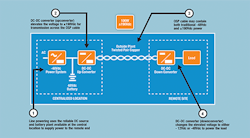
In Remote Line Power, the centralized power source starts with a conventional 48Vdc rectifier and/or battery plant. The output of the rectifier connects to an Up-converter, a special DC-DC converter that elevates the voltage to ±190Vdc for transport over the copper cables while limiting the power to 100W for safety purposes. The elevated voltage lowers the current, reducing the power lost in the cable and increasing the overall reach of the circuit. At the far end, another special DC-DC converter, called a Down-converter, changes the ±190Vdc back to 48V for powering the remote device. Figure 1 shows a block diagram of the operation.
Figure 1. Block Diagram of Remote Line Power Circuit.
While new to small cell applications, Remote Line Power has been deployed by wireline carriers for years. Most recently, it has been successfully deployed to energize CAF-II (Connect America Fund) DSLAM deployments. This technique has been a natural fit for CAF projects where existing, vacated cable pairs can be used to deliver power to low-power, sealed DSLAMs.
Unlike CAF projects, however, the Southern California project did not have the luxury of vacated cable pairs; in fact, there were no existing cables nor OSP facilities connecting the small cell end points. Still, with hard deadlines pending, it decided to investigate the feasibility of placing new copper facilities alongside the fiber already planned for each small cell site. As with many OSP projects, the results varied based on the path and the end site, but in this situation the Remote Line Power solution was financially and logistically attractive, even in areas where new copper cable was needed.
For Remote Line Power to be feasible, there were 5 fundamental requirements.
Requirement #1
The small cells had to be low power so that they required only 1 or 2 circuits, minimizing the number of Down-converters at each site.
Requirement #2
Both the small cell and the remote power Down-converter equipment had to be small, lightweight and able to mount on a strand.
Requirement #3
Based on the worst-case distances to the small cells, the smallest gauge standard OSP cable was needed to minimize material cost.
Requirement #4
The copper cable had to be installed along with the fiber to reduce the installation labor costs.
Requirement #5
Centralized power had to be placed at intermediate sites to minimize cable runs and lower the overall cost
of equipment.
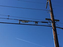
Figure 2. Small Cell and Down-Converter Mounted on a Strand.
The first criterion was satisfied by using 5W small cell radios, which consumed only 100W at 48Vdc. The radios were powered with two (2) 100W circuits delivered from a dual channel down-converter. Both the radios and down-converters were compact, lightweight, and strand-mountable. (See Figure 2.) This helped the company avoid costly pole attachment fees. The provider deployed 25-pair, 22AWG cable to each site, providing a maximum distance of 15kft (4.5km) from the centralized power location. The cable infrastructure was designed for expansion of additional radios and, ultimately, 5G deployment. By including this in the initial design criteria, future deployment costs are greatly reduced and the time frame for deployment is weeks or days rather than months or years.
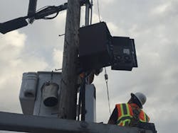
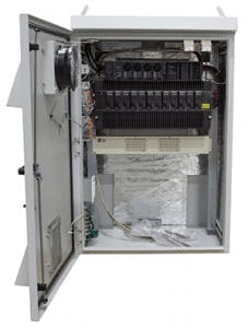
For the source power, where the rectifier, up-converter and/or batteries reside, standalone outdoor cabinets called Remote Power Node (RPN) enclosures were deployed. The weatherproof cabinets were installed in both pole and ground-mounted arrangements. The RPN included a means for terminating the AC electrical feed, a 48Vdc power system, an up-converter system, a protector panel with gas tube modules and a maintenance-free active cooling system. Two (2) different sizes of RPN enclosures were used, based on the number of circuits served circuits (an RPN typically serves 36 or more Line Power circuits). Pole and ground mount applications are shown in Figures 3A and 3B.
Figure 3A. Remote Power Node Cabinet.
While Remote Line Power was a large part of this project, local power was also used to power some of the sites when feasible. This project did not require battery backup, which further simplified the local power solutions. Even without battery backup, the company was still able to justify the cost of deploying powered copper cable to each site.
Power Viability
The Southern California project began out of necessity with no viable local power solutions for many of the sites. To overcome the problem, the Remote Line Power was chosen, consequently reducing the reliance on the local power utility. This approach proved to be a better, more economical solution while improving the company’s ability to meet the deployment schedule. In this case, over 1,000 small cells were deployed in just 14 weeks. As a comparison point, the number of installed AC-powered small cells has yet to reach that number in 30 weeks.
Figure 3B. Remote Power Node Cabinet.
Although battery backup was not required, the company was still able to justify the use of Remote Line Power. This technique reduces the number of batteries and places them in centralized, easy-to-maintain spots. Had the application required battery backup, the cost benefits would have been even more dramatic due to the reduction of ongoing operations expense. Fewer power sites also minimize the environmental impact by reducing the overall number of batteries and battery locations.
Thanks to a challenging project, one company began an option when there was no readily available source of electricity. Remote Line Power serves as a complement to local power, filling a significant gap and providing full power coverage to match the cell site network. With it, the planner and engineer can move one step closer to using cookie-cutter, standardized designs necessary to make small cell deployments routine.
Save
Save
Save
Save
Save
Save
Save
About the Author


