Bonding and Grounding: A Well-Grounded Shield

With guest writer Bill Cole —
A field technician with a high-power influence problem recently asked me how to ensure that a cable was properly bonded and grounded. I reached out to William (Bill) Cole, a retired Bell South ICEP engineer, who defined a process for how to identify a well-grounded cable shield and how to test the continuity of the shield.
An interesting backstory: Bill discovered his method while going head-to-head in a friendly competition with a respected co-worker to determine the best method for ensuring a well-grounded shield. The co-worker depended upon the Clamp-On Method while Bill used the following process, How to Identify a Well Grounded Cable Shield, (outlined in this article).
Both methods found problems but Bill’s method was more efficient and accurate. I hope this is a technique that you can add to your tool chest.
How To Identify Well-Grounded Cable Shield
The aluminum shield in communication cables is there to reduce the effect of external electrical currents on the wires in the cable. The 2 major sources of these external currents are from the power lines and lightning surges. The first line of defense against these currents is continuous well-grounded shield. That is easy to say but is difficult to achieve. This explains what a well-grounded cable shield is, the benefits of a well-grounded shield, and how to test the continuity of the shield.
The Rules Of Grounding A Shield For Noise Reduction
- A ground to the power company neutral is required at a minimum of 4 times per mile.
- … at every location where the power company MGN is available.
- … at every cross box or major junction.
Most outside plant engineers can tell you the rules, and they can follow the rules, but with many rules, there is an important back story.
Major Points
The major points of bonding and grounding to reduce power line or lightning are presented here as a review.
Major Point #1. The grounds at the beginning and end of the exposure have the highest currents.
Major Point #2. Remember this: The intermediate grounds carry the current that relates to the differences between the 2 adjacent sections of cable.
Major Point #3. Each section has voltage inducted on the shield, and the current in the shield is the result of the bonds and grounds on the shield (this will be needed later).
Major Point #4. The source that induces the voltage on the shield also induces voltage on the pairs in the cable, and the induced voltage on the pairs is reduced by the bonded and grounded shield.
Bonding and grounding reduce the effect of lighting surges, but because it is difficult to test a cable under those conditions, we can use the power line induction as an indicator of how well the cable is bonded and grounded.
Let’s Review Major Point #1: The beginning of the exposure is where the cable and the power lines are parallel to each other.
Here Is An Example That May Change That Answer
A cable that runs along a highway and at a crossroad the cable splits, with part of the cable running down the side road and the other part of the cable continuing along the highway.
- The junction is the end of 1 exposure and the beginning of 2 others. This could be a critical ground point.
- Even the change in the size of the cable could be considered the end of one exposure and the start of a new exposure, another ground point.
- A change in roadside separation is another change in exposure.
This example shows that the definition of exposures, whether beginning or end, may not be as clear as first thought.
Benefits Of A Well-Grounded Shield
As we know, external electrical currents can induce voltage in communication cables. The 2 main sources of current are power lines and lightning. Keeping these voltages at a minimum is the objective of grounding the shield of the cable.
Voltage surges from lightning can easily exceed the pair-to-pair voltage rating of the cable specifications. The shield-to-pair voltage rating is much greater than the pair-to-pair voltage rating. Keeping the lightning surge on the shield can drastically decrease the damage to the cable and the number of protectors replaced after each storm.
The induced voltage in the core of the cable is the result of the currents in the parallel power lines and the coupling to the cable. The coupling between the cable and the power line is dependent on several factors, all of which cannot be changed.
Some of these factors, which cannot be changed, are:
- The size of the cable.
- The distance between the cable and the power line.
- The conductivity of the earth.
The factor that can be controlled is the continuous bonding and grounding of the cable shield.
- A current in the shield of the cable induces a voltage in the pairs in the cable.
- For a current to flow on the shield it must be bonded and grounded.
- Reducing the amount of voltage induced on each pair in the cable reduces the amount of noise on the cable pair.
The benefits of having a well-grounded cable shield are:
- reduced noise
- fewer protector failures
- longer life of the cable
Testing The Continuity Of The Shield
Now that we have reviewed that bonding and grounding can reduce the effects of external voltage and currents, and that the location of a good ground may be more often than first thought, it is time to turn to testing the continuity and grounds of the cable shield.
A review of some of the factors involved are present here only as a review. Any wire or cable exposed to a power line inducts voltage. The induced voltage produces a current if and only if there is a path to ground.
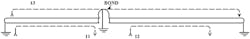
Figure 1. Currents in a multi-grounded cable shield.
Figure 1 depicts the currents in a cable shield. The induced voltage in each section gives rise to the currents I1 and I2. Because the 2 currents cannot flow in the ground at the center, only the difference between I1 and I2 flows in the center ground and the results are current I3. If there is an added resistance due to a loose or corroded shield connection in section 1 or 2, the currents are altered and show up with the test performed later.
If you have ever used a probe wire for testing, you grasp this very quickly.
For Those Who Have Not Used A Probe Wire
- It is simply a length of wire laid out under a power line with one end grounded; the other end is connected to a transmission noise set and to ground.
- A spectrum analyzer can be used in place of the noise set, and the different frequency can be reviewed.
- The number of harmonics and the predominant frequency is a study all its own.
We Use The Concept Of The Probe Wire Inside Of The Cable To Measure The Effectiveness Of The Shield.
The currents on the shield are very important, but measurement of the currents do not relate directly to the shield factor the same way the following measurements lead directly to the effectiveness of the shielding.
- SELECT A TEST LOCATION where a good ground can be placed on the cable shield and a test pair.
- AT THE NEXT ACCESS POINT IN THE CABLE, connect the noise meter to the test pair and measure the power influence under 3 conditions.
- A. Measure the power influence with the shield open.
- B. Measure the power influence with the shield bonded only.
- C. Measure the power influence with the shield bonded and grounded.
For A Good Test
The following 3 steps must be done in this sequence for a good test.
TO BEGIN:
- At the starting location, ground the shield of the cable.
- Connect the cable pair to a transmission test set.
- At the next location connect a transmission test set to the test pair.
STEP 1. Measure the power influence with the shield open. The worst condition. Record the reading.
STEP 2. Connect the 2 cable shields (bond) without a ground. Record the reading.
STEP 3. Apply a ground to the shields. Record the reading.
Measurement #1 should be the poorest, and measurement #3 should be the best. But that is not how it works in the real world.
What Would Be Good Is If
- measurement #2 were lower than measurement #1 by 12dB to 15dB, and
- measurement #3 would be slightly below measurement #2.

InvisiLight® Solution for Deploying Fiber
April 2, 2022
Go to Market Faster. Speed up Network Deployment
April 2, 2022
Episode 10: Fiber Optic Closure Specs Explained…
April 1, 2022
Food for Thought from Our 2022 ICT Visionaries
April 1, 2022THE PLACEMENT of a bond connects the section under test to the next cable section. At this point, we do not know if the shield to the field is good or bad. Be sure to record all measurements. In Figure 1, look at I3 only — ignore I1 and I2 for the time being.
A DECREASE in the reading of 15 dBrnC or more indicates that there is a reasonable ground at the other end of the cable. A marginal reading of 8-10 dBrnC indicates that there is more work ahead, and when the ground is added the ground at this location, power influence would decrease overall.
WHEN A GROUND is attached to the shield, currents I1 and I2 come into play. Normally I1 and I2 would be equal. A decrease in the reading is expected. Getting a better ground on the shield compared to the field end of the cable causes the current I1 to increase and provide better shielding. This also indicates that the field could be better, and it is found in the next section.
ADDED RESISTANCE in one of the shields causes a bigger difference in I1 and I2. A loose or corroded bond on the shield causes a decrease in the current for that section. That is the same as a decrease in the shield factor and an increase in the power influence.
IF THE GROUND IS ADDED, and the reading increases, there is less current flowing in section I1 because there is more resistance in the shield in section I1 compared to section I2. The major cause for I1 to decrease is a loose or corroded connection. Look for an access point that is hidden, such as a pedestal hidden in the weeds.
AFTER THE TEST provide a good decrease in the PI, then you are ready to move to the next section.
YOU CAN MOVE through these tests faster than you think — and at the end of the day you can say "I reduced the PI by 15 dB."
Review
- A well-grounded, and continuous shield is important to good service. Grounds at key locations are good for noise mitigation.
- Currents on a branch cable flow to the nearest ground, even if they expose the main cable to additional currents (ground the junction of the 2 cables).
- The resistance and resulting current in Section 1 (listed earlier) controls the amount of shield factor.
- If the first test appears to have good shielding and excessive noise, the root cause of your high-power influence is a power-associated problem such as an unbalanced capacitor bank, or an undersized power neutral wire, or an unbalanced three-phase power line.
With this proven data in hand, you can now confidently notify the power company that the ball is back in their court.
About Bill Cole
Beginning his career as a cable helper and as a splicer, William (Bill) Cole completed his BSEE from LSU, and subsequently joined Bell South working as an ICEP engineer in Louisiana. He then moved to Birmingham as a staff manager in transmission engineering, and then worked in the Science and Technology department for Bell South. Bill noted that while he worked many years at headquarters, "My heart was in the field."
Signing Off
As you loyal readers know, I always end with an offer to reach out to me about the column. While you are welcome to do so, Bill was very generous in offering his contact details to you so that we can further the conversation of bonding and grounding. Bill’s email is [email protected] and his cell number is 770.330.2816. Or contact me with ideas for upcoming columns or answers to your technical copper-related questions: [email protected] or 831.818.3930.
Like this Article?
Subscribe to ISE magazine and start receiving your FREE monthly copy today!
About the Author