
Powering Options for Small Cells —
To continue to meet the goal of ubiquitous 5G service, it is clear that many additional 5G nodes are needed. To support these nodes, which are comprised of radios, antennas, and transport equipment, additional transport backhaul and additional power are both needed. To meet the transport bandwidth demand, fiber is often the best choice.
To serve these sites with power, there are a few competing alternatives. You could connect each 5G node to the commercial AC power through a utility-provided metered grid connection, just as you would in your home. But providing an AC meter at every pole or site that serves as a 5G node could greatly increase the cost of deployment and installation time.
Another option is a direct utility connection without a meter. Such an approach requires less hardware and expense but still requires an agreement with the local power utility and the payment of a fixed fee to them.
Both of these options involve the powering of telecom equipment with potentially hazardous commercial AC power.
Thankfully, a safer alternative exists.

InvisiLight® Solution for Deploying Fiber
April 2, 2022
Go to Market Faster. Speed up Network Deployment
April 2, 2022
Episode 10: Fiber Optic Closure Specs Explained…
April 1, 2022
Food for Thought from Our 2022 ICT Visionaries
April 1, 2022The 5G communications provider can employ a centralized powering approach to support 5G network deployment. A centralized powering solution leverages a single connection to the commercial power grid to deliver power to multiple remotely located network elements that can be installed thousands of feet away from the centralized power source.
The concept of centralized power is nothing new to the telecommunications industry. Since the removal of the hand crank on the side of telephone sets starting in 1893, phones have been centrally powered. Nominal 48-volt power supplies located in telephone central offices have been used for delivery of POTS service for over a century.
More recently, Remote Feeding Telecommunications-Voltage limited (RFT-V) technology has been utilized to transport power at higher voltage levels to efficiently deliver greater levels of power over long distances to remote outside plant electronics. RFT-V limits the maximum power per circuit to 100 VA. Current versions of Fault Managed Power Systems (FMPSs) have adopted the same source voltage limits that apply to RFT-V; however, no limit is placed on the magnitude of power per circuit. This article explores this relatively new FMPS technology.
Even as equipment has become more energy efficient, increased demand for higher speeds and capacity has resulted in a demand for more power at the network’s edge. The need to support the proliferation of distributed communications network access elements along with increasing power consumption requirements has created a need for a cost-effective, higher-power alternative to traditional RFT-V technology.
Fortunately, at the same time, technological advancements in power distribution system fault management techniques have made it possible to transport greater magnitudes of power while significantly reducing the risk of human shock and fire hazards.
Systems that employ fault-managed power distribution technology provide for rapid fault detection and power source shutdown in the event of human contact under a wide range of line-to-ground and line-to-line fault scenarios. This technology precisely controls and minimizes the amount of fault energy that can be transferred to a person during a human contact fault event. Simply put, where traditional powering relied on lower voltage and power limits for safety, newer systems can rely on intelligent power sources to control the safety of otherwise hazardous voltages and currents.
One emerging technology combines DC power and packetized data, which is transmitted and received between power sourcing equipment (PSE) and powered devices (PDs). Other emerging technologies utilize proprietary techniques to rapidly detect any fault condition and immediately shut down the source voltage. Both methods permit higher voltages which allow efficient power transmission over much longer distances without reliance on high currents and large gauge copper wires. Both approaches provide dramatic safety improvements over conventional power distribution methods.
With the use of monitoring and control circuitry and software, these FMPSs can apply 400 volts line to line and prevent electrical injury to a communications technician who may come into contact with the system conductors. This also allows for installation of power circuits within the communications space on poles or trenches as defined by the IEEE National Electrical Safety Code (NESC).
Electrical Safety Is Paramount
Most FMPS designs employ an electronic handshake to verify that the powered device is present and operating correctly before an otherwise hazardous voltage level is applied to the line. Faults result in immediate termination of output power delivery. Digital monitoring is not a new concept or unique to these systems to control and mitigate safety risks.
There are a number of standards that rely on digital monitoring and controls in very critical safety areas, including:
- patient care equipment
- programmable circuit breakers
- commercial aviation
- mass transit
- alarm systems
The necessary requirements for functional safety are well known, and include mean time between failures of critical components, component and system level redundancy, and software reliability.
The standards community is currently working to address these new telecommunications power systems. The Alliance for Telecommunications Industry Solutions (ATIS) is preparing a technical report (TR) that defines FMPS requirements and provides the means to access any possible electric shock concerns with the use of these systems based on their ability to provide fault-managed power.
FMPSs employ several types of active elements to provide fault management functionality. In the context of the ATIS TR, the following definitions apply:
- Power Sourcing Equipment (PSE) — Telecommunications equipment supplying fault-managed DC power to remotely located powered devices (PDs). The PSE shall provide power and fault management functionality when connected to a PD specifically designed to be used with the PSE. The PSE shall not produce current unless it is connected to a PD specifically designed for use with the PSE.
- Powered Device (PD) — Telecommunications equipment designed to be paired with a specific PSE design to facilitate the fault management functionality of a fault-managed power system. PD power output is intended to provide non-fault-managed power for remotely located telecommunications equipment. A PD can be a stand-alone device or integrated directly into the enclosure of a telecommunications network element.
- Junction Box (JB) — A junction box is a transmission line mounted device that is used in a bus configuration to terminate PD(s) and create shorter cable segments of fault managed power. The junction box is a PSE-like device in that it provides fault energy management but differs because it does not act as a power source.
Fault Managed Power System configurations covered by the TR are divided into 2 broad categories:
- Point-to-point configuration — Single PSE connected to a single PD by one or more power cable pairs.
- Bus configuration — Single PSE connected to multiple PDs by one or more power cable pairs. A bus can consist of a PSE and multiple junction boxes and PDs connected along a single conductive path between the PSE and PDs (a serial arrangement), and can also include branch conductive paths between the PSE, Junction Boxes, and PDs (a star arrangement).
Point-to-point Fault Managed Power Systems are comprised of 3 sections consisting of a power input section, a power transport section, and a power output section. Fault management functionality is limited to the power transport section as illustrated in Figures 1 and 2. The power transport section is comprised of the PSE output terminals, the power cable connecting the PSE to the PD and the PD input terminals. Fault management requirements and testing presented in the ATIS TR are limited to the power transport section of fault managed power systems.
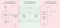
Figure 1. Fault-Managed and Non-Fault-Managed Portions of a Point-to-Point FMPS.
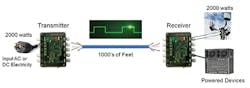
Figure 2. Point-to-Point Fault Managed Power System Diagram with a Total Power of 2,000 Watts at the Far End.
Point-to-multipoint or bus-configured Fault Managed Power Systems are comprised of 4 basic sections consisting of power sourcing equipment, power transport, junction boxes for bus to bus or PD termination points, and powered devices. (See Figure 3.) Fault management functionality is limited to the power transport sections as shown in Figures 1 and 3. The power transport sections are comprised of the PSE output and the power cable connecting the PSE to subsequent junction boxes and powered devices. Figure 4 shows both a point-to-point and point-to-multiport system.
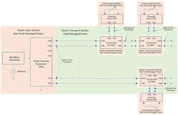
Figure 3. Fault Managed and Non-Fault Managed Portions of a Bus Configured FMPS.

Figure 4. Overall View of a Point-to-Point and Point-to-Multipoint Systems (e.g., the JB and PD can represent a 4G/5G small cell location).
- Additional standards work includes revisions to the National Electrical Code (NEC) needed to realize the full potential of this emerging technology. The technology will be referred to as Class 4 power in a new NEC Article 726 and has been publicly referred to by several names including Packet Energy Transfer (PET), Digital Electricity (DE), Pulsed Power, Smart Transfer Systems, and Fault Managed Power (FMP), among others.
- Underwriters Laboratory (UL) is looking to develop requirements for Nationally Recognized Test Lab (NRTL) Listing of Fault Managed Power Systems that focus on reducing the risks of electric shock and fire associated with their deployment.
- Safety concerns to address include electric shock, available fault energy, functional safety, and cable design and construction.
- To assess the risk of electric shock, the industry will look to International Electrotechnical Commission standard IEC 60479-1: Effects of current on human beings and livestock: Part 1: General aspects; and Part 2: Special aspects.
- A centralized FMPS powering approach provides several advantages over other 5G small cell powering techniques. Combining both power and transport into a single hybrid cable reduces construction cost, and requires less space and reduced wind and ice loading on joint-use utility poles. Reducing the number of power grid connections reduces both cost and lead time for small ce0621ll deployment.
- The employment of up to 400 volts line-to-line reduces current draw, resulting in lower power line losses over long distances. This centralized powering solution also facilitates the provisioning of a centralized battery backup or generator standby power system, avoiding the need to install reserve power at each node. All this leads to reduced installation costs and time, and more flexible site selection as well as craft friendly installation and operation.
5G technology provides dramatically increased bandwidth along with significantly reduced latency well beyond what current LTE mobile technology permits. By extending the reach of mobile broadband, 5G can power technology well beyond what current mobile technology permits. However, the 5G radios and small cells require safe, cost-effective, reliable power. The key is to harvest the best 5G powering strategies for the future — whether in the outside plant or in buildings, train stations, or sport stadiums.
For more information, please email [email protected] or visit https://www.ericsson.com/en. Follow Ericsson on Twitter @ericsson.
Like this Article?
Subscribe to ISE magazine and start receiving your FREE monthly copy today!
About the Author

Ernie Gallo
Principal Outside Plant and Electrical Code Consultant, NEBScore
Background • 44+ years experience in Telecom Industry • 7.5 Years Underwriters Laboratories • 33 Years Bellcore-Telcordia-Ericsson • BSEE Polytechnic University of New York Consulting Focus Areas • Electrical Safety, Electrical Protection • FCC Infrastructure Sharing During Emergencies • Outside Plant Product and Installation Standards and Audit Analytics • Industry Standards and Code Compliance – Regulatory and Safety – construction focused • Fiber to the Home – micro-trench and MDU architecture • Fiber to the Node – VDSL to the home • Wireless Products and Installation Methods • Fiber and 5G Wireless product requirements • Optical Transport Networks –Deployment Designs • Working with local Authorities Having Jurisdiction on Electrical and Fire Codes • Electrical and Fire incidents and evaluations • Expert Witness in the areas of outside plant construction and safety Industry and Project Experience Standards Work National Fire Protection Association (NFPA) • NFPA 1 Fire Code - Committee Member • NFPA 70 National Electrical Code (NEC) - Committee Member CMP1, CMP 16and Correlating Committee Member NFPA 70E -Standard for Electrical Safety in the Workplace - Committee Member • NFPA 780 Standard for the Installation of Lightning Protection - Committee Member • NFPA 855 Standard for the Installation of Energy Storage Systems - Committee Member • NFPA 75, Standard for the Protection of Information Technology Equipment - Committee Member • 2022 Committee Service Award from the Standards Council of the National Fire Protection Association (NFPA) Institute of Electrical and Electronics Engineers (IEEE) • IEEE C2 National Electrical Safety Code - Committee Member, Subcommittees SC2, SC4, SC5, and SC8 • IEEE Wire Line Subcommittee – Vice Chair • IEEE Working Group 3.6.7 Low Voltage Data, Communications and Signaling Circuit Surge Protective Devices – Chair • IEEE Working Group 3.6.10 Surge Protection of Equipment Connected to Both Low Voltage AC Power and Communication Circuits – Vice Chair • IEEE Fiber Optics Subcommittee - Committee Member Association for Telecommunications Industry Solutions (ATIS) • ATIS Board Member • ATIS Protection Engineers Group (PEG) Chair and current Advisory Board Member • ATIS STEP: Sustainability in Telecom: Energy and Protection Committee – Vice Chair • ATIS Network Power Systems (NPS) – Chair • ATIS Network Physical Protection (NPP) - Working Group Member • ATIS Network Electrical Protection (NEP) –Chair Underwriters Laboratories (UL) • Fault Managed Power Working Group UL1400 - Committee Member • Lightning Protection Components UL 96, 96A Lightning Protection Components - Committee Member • UL 497 Standard for Protectors for Communications • UL 1449 Standard for Surge Protective Devices - Committee Member • CAN/US Technical Harmonization Committee UL 62368 Standard
Ernie serves as ATIS PEG Chair. Please see https://peg.atis.org for details.