Troubleshooting Optical Splitters

Optical splitters in the outside plant (OSP) are used mostly in passive optical networks (PONs) for fiber-to-the-user (FTTx) networks, and are often overlooked as failure points. In this article I focus on a few basics of optical splitters, their applications, typical causes of failures, and how to test and troubleshoot them.
2 Types of Optical Splitters
There are 2 types of optical splitters used in FTTx installations:
• Fused Biconical Tapered (FBT)
• Planar Lightwave Circuit (PLC)
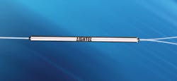
A 1:2 FBT splitter with SC/UPC pigtails. (Photo courtesy of Lightel)
PLC splitters are more complex and require extensive environmental testing during manufacturing. (Graphic courtesy of Senko Advanced Components)
Both of these types are commonly integrated into modules which they can strategically be installed into panels, splice closures, and pedestals, which are located throughout the physical plant.
Both types have been successfully deployed for decades in equipment and the OSP.
Failures
Most failures tend to be in the OSP, and are caused by improper installations which can be caused by microbends, splices, connector damage, and improper fiber management. Splitter failures can also be intrinsic, which we’ll address.
Industry Standards
One of the reasons the fiber industry has decades of experience with optical splitters is the compliance with industry standards. The most common are:
• the ITU-T G.671 Fiber Optic Passive Components standard, which focuses on FTTX (FTTH & FTTB) applications.
• the Telcordia general recommendations, GR-1209 & GR-1221, which outline the generic criteria for passive optical components to ensure continuous operation of the components over various conditions over their lifetime.
Included in these standards are the general requirements for an OSP component, the functional design criteria, and its performance criteria.
These standards also provide the various values used in the loss budgets for the optical line terminals (OLTs) and optical network terminals (ONTs).
Fused Biconical Taper (FBT) Splitters
Understanding the types of optical splitters and how they are manufactured allows us to identify potential intrinsic problems that can occur.
The Fused Biconical Taper (FBT) splitters are fabricated by heating 2 optical fibers until they coalesce into a composite waveguiding structure. While the fibers are being heated, they are slowly stretched and tapered. This causes the light in the fiber to spread out far enough into the composite structure where it can be coupled to the other fiber.
During this process, light is launched into the input fibers while a process control computer monitors the outputs and adjusts pull tension, fusion temperature and duration. In this way, the desired coupling ratio between fibers is achieved. FBT splitters are normally used in small split counts and also where tapered (e.g., 10/90%) splitters are desired.
The completed coupler is then sealed in a protective enclosure, which usually consists of a metal tube placed around the fused section of bare fibers, and held in place with an adhesive. 250- or 900-micron-coated fiber pigtails extend through the ends of the package.
While all the splitters are tested, should a microcrack occur during the fiber preparation stage, it may pass through the optical testing stages yet may fracture later caused by environmental thermal stresses.

InvisiLight® Solution for Deploying Fiber
April 2, 2022
Go to Market Faster. Speed up Network Deployment
April 2, 2022
Episode 10: Fiber Optic Closure Specs Explained…
April 1, 2022
Food for Thought from Our 2022 ICT Visionaries
April 1, 2022Planar Lightwave Circuit (PLC) Splitters
The second type of optical splitter is known as the Planar Lightwave Circuit, or PLC.
The development and manufacture of the PLC was the direct result of semiconductor technology associated with the computer processor and surface-mount electronics. Mass production of the PLC splitters can be accomplished in the same manner.
Like optical fibers, PLCs confine light in a region of high refractive index surrounded by material with a lower refractive index. The waveguide could be a strip embedded in a flat substrate, or it could be a strip deposited on the surface of the substrate.
Waveguide patterns are written using the same techniques that write integrated circuits onto semiconductor wafers. They can branch, or merge, or can be cascaded to form couplers with more ports. Multiple parts can be written to each wafer, then cut into individual components. For this reason PLCs are mostly used in high split counts, whereas FBTs are normally used in smaller splitter counts.
Attaching fibers to the planar splitters requires that V-grooves be etched into the substrate material. The fibers are placed into these grooves, aligned and then fixed in place with a cover block made from the substrate material. The planar coupler is smaller, has higher splitter counts and shows slightly lower losses than FBT splitters.
Internal problems can include damaged waveguides, broken fibers, delamination, and unsecured splitter housing. This point on the waveguide increases the light scattering effect, thus increasing the return loss and increases the attenuation.
As with the FBT types, a broken fiber within the fiber array v-groove is usually caused by imperfect fiber stripping, cleaning, and cleaving, of the ribbon fiber during the manufacturing process. A small scratch or crack on the optical fiber can become a stress point during the resin curing process or from prolong usage where it may be subjected to temperature fluctuations or vibrations.
Key to PLCs is the attention to detail in manufacturing and packaging to address expansion and contraction on the different layers of substrate materials caused by environmental changes at extreme temperatures. Major attention is used to insure fiber end-face quality is performed as there are multiple internal splice points.
With this compact packaging arrangement, the couplers can be mounted inside electronic equipment, and splice trays can be placed inside modules where their pigtails can be terminated by connectors. Such modules are convenient for mounting in racks or cabinets, including those used in FTTx installations,
Cause of Failures
Now that we understand how splitters are manufactured we can look at the cause of their failures. As most manufacturers have stringent test procedures, we can identify intrinsic losses that are caused mostly by environmental stresses that can start with a microcrack caused during the fibers stripping and cleaving procedures. Even after thermal testing these may take years to fail but when they do, they can affect one to multiple locations.
Depending on where they are located, and the number of subscribers affected, this dictates the type of equipment used to identify and locate the culprit splitter. First the operation, administration, maintenance and provisioning (OAM&P) functions of the PON’s OLT and ONTs will alarm. Using a 32 port G-PON as an example, the following scenarios are applicable to troubleshoot and identify problem splitters.
Scenarios
If the splitter is placed at the central office (CO,) known as a home run topology, and all 32 subscribers are out of service, the failure could be caused at the input port of the splitter, the jumper from the OLT, or from the OLT itself. In this case use an optical power meter (OPM) and test the input port of the splitter for the optical power level (dBm) from the OLT at 1490 nm. If there is no or reduced power then the patchcord or OLT is the culprit. If the power level is reduced it could be as simple as a microbend or macrobend.
For those who have placed the splitter using a centralized architecture where a 1:32 splitter is located in one location in the OSP and all 32 subscribers are in alarm, then you can use an OTDR from your CO to confirm the fault is at the splitter. If there are multiple PONs in alarm then the suspect could be cable damage in the OSP. A single ONT outage though points to the individual ONT, the optical splitters output port or the fiber drop in between.
If only one ONT is offline, then an OPM could be used to confirm the output power level. In this case start at the ONT and work back to the splitter. This would identify whether the ONT is receiving the required amount of optical power. If not, then work back to the splitter checking optical power levels in dBm.
For those having a distributed or cascaded architecture with multiple splitters in the OSP, we are depending on alarms at the OLT to identify the extent of the impact and how many users are affected. For example, if it is only 1 subscriber, then the same process is used as above. However, if 4 subscribers are in alarm, then if the PON is using a 1:8 splitter linking to four 1:4 splitters, then the 1:4 splitter is suspect. First, using the OPM, check the input power level of the splitter. If there is no power, the problem would be the fiber in between the 1:8 and the 1:4 or the output port of the 1:8 splitter. Again, the OPM is your best tool for verification.
Recommendations
When first installing the PON, document the output power level at the OLT, the input level of each splitter along with the output levels. These will help tremendously when checking power levels to identify any changes since the initial construction.
Like this Article?
Subscribe to ISE magazine and start receiving your FREE monthly copy today!
Summary
Optical splitters have been used for decades in fiber optic systems and test equipment. Their reliability has been outstanding, yet failures can occur. It is important that you purchase your splitters from reputable suppliers as they have extensive quality control procedures used to verify performance during the manufacturing stages in order to minimize future problems.
About the Author