Building It So THEY Will Come —
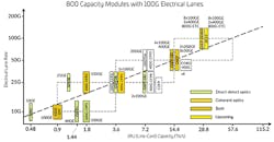
Switching speeds are changing, with serialized/deserialized (SERDES) speeds stepping quickly from 10G through 25G, 50G to 100G, and perhaps 200G in the future. (See Figure 1.)
Figure 1. Optics and SERDES speeds increase in lock step. (Source: Juniper Networks)
Higher switching speeds drive higher network speeds, which naturally favor fiber optic network links. In turn, the SERDES speeds of network switches tend to determine the speed that servers are attached to the network. Matching speeds end-to-end provides the most cost-effective solution.
To support faster speeds and boost efficiency, switches are increasing in port density (a.k.a. radix) and moving from a top-of-rack (ToR) topology to either middle-of-row (MoR) or end-of-row (EoR) configuration. As a result, the ability to manage the large number of server attachments with greater efficiency is becoming critical.
Accommodating this need in the server row requires new optic modules and structured cabling, such as those defined in the IEEE802.3cm standard. Among other things, IEEE802.3cm describes the benefits of pluggable transceivers for use with high-speed server network applications in large data centers.
InvisiLight® Solution for Deploying Fiber
April 2, 2022Go to Market Faster. Speed up Network Deployment
April 2, 2022Episode 10: Fiber Optic Closure Specs Explained…
April 1, 2022Food for Thought from Our 2022 ICT Visionaries
April 1, 2022The changes in server row compliments the evolution of switch radix and switch capacity. Driven by the need for greater efficiency, networks are deploying higher radix application-specific integrated circuits (ASICs). Increasing the ASIC input/output capability supports more network device connections and reduces the number of switches needed for a cloud network. As the ASIC switch radix increases, EoR or MoR topologies improve management of the large number of server attachments. This structured cabling design provides for rack-and-stack server deployments.
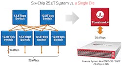
At the same time, reductions in both the number of network switches and switching latency are increasing the efficiency of switch capacity, as seen in Figure 2. Improvements in switch radix and capacity continue to evolve at a rapid pace, helping to optimize DC efficiency.
Figure 2. Streamlining the switch layer increases switch capacity efficiency. (Source: Broadcom)
Cloud Networks Impact Design
Cloud networks contain a large number of edge devices, which require a high number of optic connections, preferably at a low cost. Low-cost pluggable modules and structured cabling reduce overall costs supporting next-generation server connections, helping to overcoming issues associated with the deployment of Active Optical Cables (AOCs) and Direct Attach Cables (DACs) at new higher speeds.
The need for low-cost optics and the reduced length between server connections — generally less than 100m and often less than 50m — are driving the development of a multimode fiber (MMF) transceiver with optic applications that can support both switch-to-switch and switch-to-server configurations.
Multimode continues to provide the most cost-effective system costs when link lengths are short.
Figure 3 shows the benefits of selecting a high bandwidth MMF. As speeds increase, options for shortwave division multiplexing (SWDM) enable more efficient use of fibers with a greater variety of wavelengths. OM4 and OM5 cabling also help network managers address issues regarding higher bandwidth complexity and extended link distances. The latter is especially important as the 150m reach of OM4/OM5 supports longer switch-to-switch connections.
Figure 3. 400G improves fiber-use efficiency and link distances. (Source: CommScope)
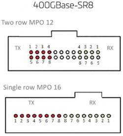
The IEEE 802.3cm standard also introduces 2 MMF server connection types — supporting 16 fibers (8 fiber pairs), as shown in Figure 4. As discussed earlier, this allows for individual server connections that can vary based on the number of 50G lanes assigned to the link (e.g., 50G, 100G, 200G). Structured cabling solutions are supporting this in-row topology, providing the flexibility to support flexible breakout mapping (N*lane-rate). The basic design is now based on octal modules instead of the previous QSFP modules. This change includes logical mapping of existing 12-fiber and 24-fiber cabling commonly deployed with previous QSFP generations.
Figure 4. MPO 12/MPO16 connector interfaces for 400GBASE-SR8. (Source: IEEE Standards Association, 802.3cm)
On to 800G?
The introduction of 100G I/Os will double switch port speeds. The same 400G cabling strategies and higher bandwidth MMF can support this transition to 800G modules. The IEEE 802.3db task force is now working on a new transceiver standard to support the 100G transmission on a single wavelength over 100m of OM4 fiber. For shorter links, lessnthan 50m, the task force is also exploring the potential for a very-low-cost option.
Capitalizing on the octal module and the introduction of 100G electrical lanes, a new MSA has been formed to develop 800G optic applications. The MSA participants began by assuming 100G would require SMF to the servers. While it is still early, many believe that short links will again favor low-cost MMF VCSELs vs. SiP and SM lasers. However, an 800G module does not necessarily mean a new 800G MAC rate. So, the IEEE has launched a study group to help transition to the next plateau of higher Ethernet rates. 800G is likely on the map, and a path to 1.6T and beyond is also being explored. As 800G development begins, new optic modules will be introduced. Figure 5 lists some of the popular optic modules that may be employed.
Figure 5. Potential optical modules for 800G applications. (Source: Juniper Networks)
800G and Beyond
As data centers, service providers and enterprise network managers navigate the inevitable changes in their physical layer infrastructure, their strategies will be impacted by the following trends:
- The nature of switches is changing: Driven mby the need for greater efficiency, networks are deploying larger radix ASICS and switching.
- Speeds will increase quickly: Server refresh cycles should be aligned with the expected introduction of faster switching speeds as 50G and 100G SERDES are incorporated into server NICs.
- Server-topologies are changing: Networks managers should plan a path to 16-fiber deployments, matching the octal QSFP-DD and OSFP transceiver modules.
- Benefits of structured cabling in server rows: Compared to AOCs and DACs, structured cabling is migration-proof and is well-suited to the increased densities that high radix switches offer.
- Continued need for high-quality optics: As network speeds increase, so does the demand for higher bandwidth (think OM5 MMF) and lower losses.
- MMF has a long future in the data center: Prompted by the growth of hyperscale environments, the industry continues to develop new transceivers for short reach applications. As always, VCSEL technology continues to shine for these short reach applications.
Using these trends as guide rails, network managers will be better able to keep their infrastructures future-ready yet fully capable of satisfying the current demand for speed, efficiency, and performance.
Resources and Notes
https://www.800gmsa.com/
https://www.ieee802.org/3/B400G/index.html
For more information, visit https://www.commscope.com/. Follow James on Twitter @10gnyou.


